Small transmitting loops (STL) are very popular with hams, and a fashion is developing for N turn loops. This article lays out some thoughts on a 2 turn STL.
Firstly, to the meaning of “small transmitting loop’. There are a range of definitions used, and they mostly centre around the concept of a size sufficiently small that current is approximately uniform. The issue is about the meaning of sufficiently. Accuracy of estimation of radiation resistance of small transmitting loops sets out a rationale for a single turn loop for criteria that perimeter<λ/10.
This article will compare NEC-4.2 models of loops with the following key parameters:
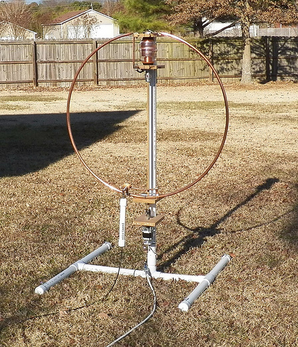
- 1m diameter (the loop perimeter is 0.07λ);
- 20mm copper conductor;
- frequency is nominally 7.1MHz;
- 16 segments per turn
- when not specified as in free space, the loop centre is 1m above ‘average’ ground (σ=0.005, εr=13);
- the loop is directly fed in the middle, opposite to the tuning capacitor position, cap down;
- pitch is 0.15m.
The model is sensitive to all these parameters. Continue reading Some thoughts on a two turn small transmitting loop