Non-resonant dipole with two wire feed line and T match ATU discussed some of the issues with the common multi band configuration with emphasis on the lower bands where ATU losses can be sufficient to cause internal damage.
This article explores a scenario that came up in discussion with another ham.
His scenario is a moderately long dipole (just under λ/2) fed with a moderately long length of nominal 450Ω windowed ladder line… I am being obscure, but I don’t want to dwell on the details from that angle. This is not a case of someone loading up the roof rain gutters, or window frames, it is a serious antenna.
The chap is using a MFJ-941E ATU, which appears to use the same componentry as the MFJ-949E with which I am very familiar, the 941E appears to be a version of the 949E without internal dummy load.
So, he was able to get a good match easily using the internal balun (4:1 voltage balun), and from the settings we can estimate the matching and particularly the losses.
A model
I have separately come to a view that the Q of the 949E inductor at ‘A’ switch position is about 170 @ 1.8MHz. I also measured the magnetising impedance of the balun, it was 2.8+j350Ω @ 1.8MHz.
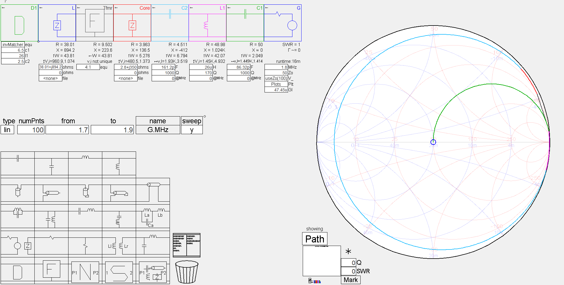
Above is a model capturing:
- the user’s reported C and L settings (assuming that 1.F=((1-c1/10)*0.9+0.1)*208e-12; etc);
- Ql estimated from measurement to be 170;
- Q of C1 and C2 assumed to be 1000;
- Core models the magnetising impedance measured (2.8+j350Ω);
- The 4:1 balun is assumed ideal other than the magnetising impedance above.
Analysis
The model has the source set to 100W, so the reported power levels are those that might be expected from continuous FT8 operation, but in practice, duty cycle would reduce the average power.
So, the headline metric is that just 44% of the 100W source reaches the feed line terminals, 56W is lost inside the ATU:
- 2W in C1;
- 42W in the inductor;
- 6.8W in C2; and
- 5.3W in the balun core.
Of great concern is the power lost in the inductor.
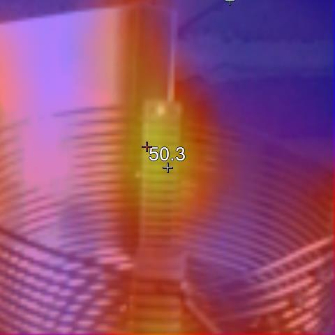
Above is a pic from Improved cooling for the MFJ-949E, it is not of this scenario but demonstrates coil heating. The thermoplastic coil supports have increased from 20° to 50° and the test was terminated at that time to protect the coil supports from damage. The coil supports are probably polystyrene, and though the glass transition temperature of polystyrene is 100°, the spot temperature may be higher than indicated and it may not be safe to run this power level for very long, especially at elevated ambient temperature.
I have repaired these for other people, and I have tested and measured my own. From that experience, I would expect that the modelled 42W of dissipation would cause softening and deformation of the coil support in just minutes.
The baluns in these can get hot, but appear to be wound with PTFE insulated wire so will withstand quite high temperature.
The capacitors are unlikely to be damaged at the calculated loss.
The Achilles heel of these ATUs is the inductor. To some extent, the step switched inductor tends to present a less efficient match, the rather small C1 and C2 drive higher inductance loss (see Optimum length of ladder line).
You might think that a variable inductor solves the problems, but they tend to have lower Q than that of this inductor. An ATU with continuously variable inductor may have larger C1 and C2 and they may significantly improve things (despite the lower Q inductor).
A mention of voltage, the voltage at the output terminals @ 100W in to the ATU, 44W into the feed line, is 961Vrms, or 1.36kVp. This is moderately high. See Avoiding flashover in baluns and ATUs.
Conclusions
On the lower bands, losses in the common T match ATU can be large enough to risk component damage when high average power is used (high power and / or high duty cycle), and this is so in this case.
Output terminal voltage in this case is moderately high, and warrants careful routing of the feed line.