Hams tend to not share a common meaning for terms, and in defence will say that anything is ok so long as the author makes their meaning clear. The latter is a huge burden in online discussions where a post may be less than 50 words.
Tom Rauch states:
Radiation resistance is both the most useful and the least useful antenna-related term. Radiation resistance can easily be misused and rendered useless. This is because radiation resistance has multiple poorly-defined meanings. When a term has several nebulous meanings or uses, it is only natural that misuse or mixing of terms appear. Lack of a firm, single, well-accepted, definition allows the term “radiation resistance” to slip from one definition into another. This often results in well-intentioned, but totally erroneous conclusions, that seem to follow accurate, logical, thought!
Roy Lewallen recently posted the following online clarifying an earlier post:
There are several different and distinct sources of loss in an antenna system that reduce the field strength at a remote point (in addition to feed line and matching system losses):
A. Resistive loss in the radiator wires and any inserted loading coils, traps, or stubs. This is usually a function of frequency due to the change in skin depth. All these, including the frequency dependence, can be included or set to zero in an EZNEC model. Wire resistance itself is seldom significant, but the resistance of loading coils in electrically short antennas, and of traps, can be. This loss factor will add resistance at the feed point, and the power loss is the square of the feed point current times this added resistance.
B. Loss due to the field’s “reflection from” (interaction with) the ground. This is typically much greater with vertically than horizontally polarized waves, and is a function of ground characteristics, frequency, and elevation angle. The reflection, particularly for low elevation angles, usually takes place far beyond any reasonable radial wire system, so isn’t affected by the radials. This loss does not significantly modify the feed point resistance.
C. In the case of grounded antennas like ground mounted verticals, half slopers, and the like, or verticals with very low radial wires, resistive loss due to current flowing in the ground radially from the ground connection. Remember that if one amp flows into a grounded antenna’s radiator, one amp has to flow from the other feed line conductor to the ground. If the radials are elevated very slightly above the ground, there’s no direct “connection” to the ground, but currents are induced by coupling from the radials, resulting in currents in the Earth that are similar to those if the radials were buried. (Note that the radial current distribution is different, so this is just a rough approximation.) This loss has the same effect at the feed point as factor A above.
“Antenna efficiency” generally includes factor A and, if present, factor C — but not factor B. It can be calculated as:
Efficiency = Rr / (Rr + Rl) where
Rr = the radiation resistance (feed point resistance with no loss)
Rl = the sum of factor A and C resistances.So let’s see how to separate these out with EZNEC. I’m ignoring the wire loss here; it would be easy to determine its loss separately.
Your example 1 file includes some resistive wire loss which is part of factor A above, but connecting the antenna to perfect ground causes factors B and C to be zero. The reported Average Gain is -0.03 dB, and with the wire loss set to zero it’s -0.01 dB.
That is more than 400 words and demonstrates my point of the burden of explanation of meaning.
But, the explanation is interesting.
To discuss this, I need to declare my meaning of some terms to be used.
Radiation: the lossless dispersion of EM energy through space, lossless to mean that whilst energy spreads over a sphere of area A at radius r, \(A=4 \pi r^2\), no energy is lost. This implies that power density \(S \propto \frac1{r^2}\) and electric field strength \(E \propto \frac1{r}\). The region where the latter is true is often called the Far Field.
Radiation Efficiency of an antenna or antenna system: the ratio of the total far field power at some distance r in the Far Field to the input power to the antenna / antenna system as qualified. This is equivalent to the gain in the far field averaged over the sphere (4 π sr).
Let’s try an NEC-4.2 model of a 10m long thin vertical dipole, 6m centre height at 14.4MHz over three ground types:
- perfectly conducting earth;
- ‘average ground’ (σ=0.005, εr=13); and
- ‘good ground’ (σ=0.015, εr=17).
NEC-4.2 sums the power in the far field, calculates the input power at the feed point, calculates the input impedance, and calculates the gain averaged over the hemisphere (in this case). We can calculate the Radiation Efficiency as the gain averaged over the hemisphere divided by 2.
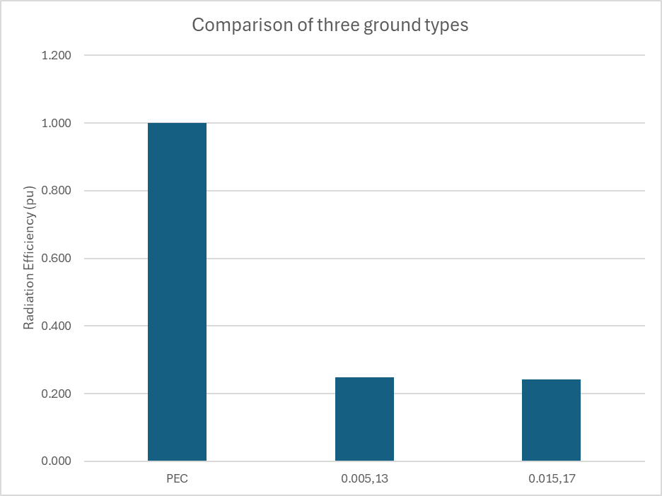
Above is a chart of the Radiation Efficiency of the three configurations.
We can consider that since \(P_{in}=I_{in}^2 R_{in}\) that Rin comprises two series components, Rloss and Rradiation that carry the same current, so \(P \propto R\) for each element.
We can apportion the power to each element and derive \(R_{radiation}=G_{avg}*R_{in}\).
Let’s examine the pattern plots for the three scenarios.
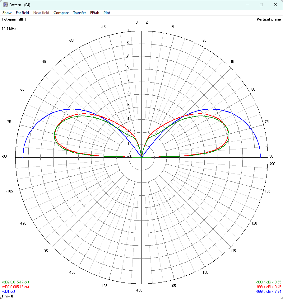
The patterns for the two real ground scenarios are similar, but not quite equal.
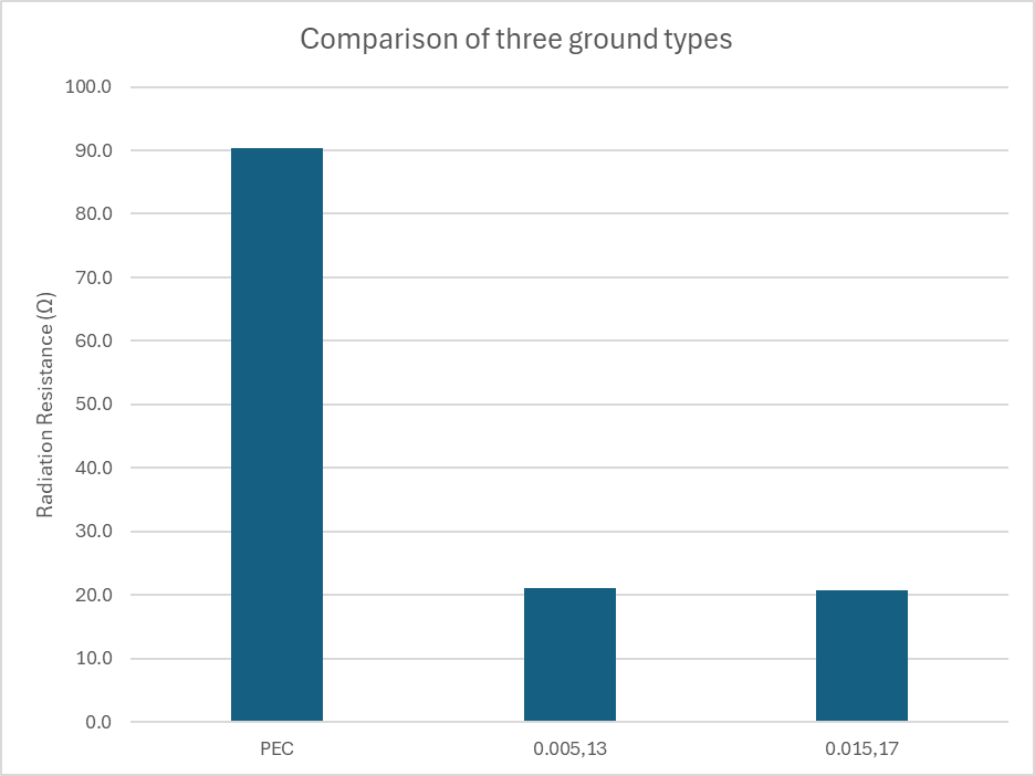
From the Radiation Efficiency and Rin, we can calculate Radiation Resistance. Again the two ground scenarios are similar, but not quite equal.
Importantly, the Radiation Resistance as I define it, is very different for the real ground scenarios than a lossless / perfectly conducting earth.
Lewallen’s assertion Rr = the radiation resistance (feed point resistance with no loss)
defines an Rr term that is specific to the lossless antenna scenario and really has no application other than discussions about lossless antennas (since the component of Rin that accounts for radiated power in real antennas may vary with various system losses), and you cannot infer the component of Rin that accounts for radiated power for a real antenna from Lewallen’s Rr.
So if I asked what is the Radiation Resistance of a lossless half wave dipole, I expect most people with answer instantly 73Ω (or thereabouts). 73Ω is correct for a lossless half wave dipole in free space, and it may be true for some other scenarios, but it does not apply generally, I have just shown three scenarios with Radiation Resistance 90.4, 21.0 and 20.8Ω (according to my definition of Radiation Resistance).
Returning to Lewallen’s formula:
Efficiency = Rr / (Rr + Rl) where
Rr = the radiation resistance (feed point resistance with no loss)
Rl = the sum of factor A and C resistances.
Given \(R_l=R_{in}-R_r\), in this case Rin of the real antennas (ie with factor A and C resistances, Rl) is less than Lewallen’s Rr, Rl is negative and \(I^2 R_l\) will be negative which does not make sense.
Users of Lewallen’s Rr and his formula for “Efficiency” may come up with some wrong results.
For example, for the second case discussed here, \(R_l=R_{in}-R_r=84.7-90.4=-5.7\) and \(\eta=\frac{R_r}{R_r+R_l}=\frac{90.4}{90.4+-5.7}=1.067 \text{ pu}=106.7 \text{ %}\). Efficiency over 100%… Lewallen’s method is nonsense.
As Rauch notes, there are other meanings in common use.