This article is a remeasure of NanoVNA-H4 – a ferrite cored test inductor impedance measurement – s11 reflection vs s21 series vs s21 pi using a VNWA-3E of both a good and sub-optimal test fixture estimating common mode choke impedance by three different measurement techniques:
- s11 shunt (or reflection);
- s21 series through
- s21 series pi;
Citing numerous HP (and successor) references, hams tend to favor the more complicated s21 series techniques even though the instruments they are using may be subject to uncorrected Port 1 and Port 2 mismatch errors. “If it is more complicated, it just has to be better!”
s21 series pi is popularly know as the “y21 method” (The Y21 Method of Measuring Common-Mode Impedance), but series pi better describes the assumed DUT topology.
What is an inductor?
Above is the test inductor, enamelled wire on an acrylic tube, an air cored solenoid.
We speak naively of this sort of component as an inductor, perhaps thinking it is a frequency independent inductance with perhaps some small series resistance. Let me make the distinction, Inductance is a property, Inductor is a practical thing (that includes Inductance… that might be a function of some variables).
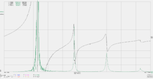
Above is an s11 reflection measurement of the impedance of the air cored solenoid.
Above, focusing below about 5MHz, R is very low and X is approximately proportional to frequency, and the calculated equivalent series L is approximately independent of frequency… so the naive model discussed earlier might be adequate. Measured inductance at 1kHz is 20µH, at 5MHz apparent series inductance is still close to 20µH, but then starts rising, more quickly as the first resonance is approached (see previous plot).
We can calculate a value of shunt C that will resonate the inductor at this first resonance, in this case it is 1.02pF (often referred to as Cse). The parallel combination of 20µH and 1.02pF will have an impedance that is a good approximation of what was measured up to perhaps 1.2 times the frequency of the first resonance, BUT NOT ABOVE THAT. Such an equivalent circuit is useful, be be mindful of the acceptable frequency range.
The existence of higher order resonances shows that this is not simply an inductance. Calculated Cse will not explain the impedance curve much above the first resonance, it will NOT explain higher order resonances.
Understand the nature of the DUT
The DUT is a small test inductor, 6t on a Fair-rite 2843000202 binocular core (BN43-202).
We speak naively of this sort of component as an inductor, perhaps thinking it is a frequency independent inductance with perhaps some small series resistance.
You might look up the Al parameter for the core and calculate its inductance to be \(L=A_l n^2=2200*36=79,200 \text{ nH}\) and calculate its impedance @ 10MHz \(Z=\jmath 2 \pi f L=\jmath 2 \pi \text{ 1e7} \text{ 79.2e-6}=\jmath 4976\).
In fact it measures 3206+j1904, so the notion of a fixed inductance with small series resistance is not an adequate model for this component at HF. It exibits a first resonance at about 16.3MhHz.
In fact the DUT is a resonator, plotted here around its first resonance.
Using a ferrite core that is both lossy and frequency dependent permeability might make higher order resonances harder to observe, they are not simply harmonically related and they may be severely damped.
The test fixture
The test uses a small test inductor, 6t on a Fair-rite 2843000202 binocular core (BN43-202) and a small test board, everything designed to minimise parasitics. This inductor has quite similar common mode impedance to a HF good antenna common mode chokes.
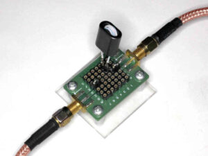
Above is the SDR-KITS VNWA testboard.
The nanoVNA-H4 v4.3 was calibrated using the test board and its associated OSL components. The calibration / correction corrects Port 1 and Port 2 mismatch error. The test board is used without any additional attenuators, it is directly connected to the nanoVNA-H using 300mm RG400 fly leads.
Above, the test inductor mounted in the s11 shunt measurement position.
Above is the sub-optimal test setup, the DUT is connected by the green and white wires, each 100mm long.
Measurements and interpretation
Optimal
Above are the results of the three impedance measurement techniques.
Note that s21 series through and s21 series pi show no significant difference.
There is a difference between the s11 shunt method and the s21 series methods, the self resonant frequency is slightly different.
Sub-optimal
It is often held that the series pi or Y21 method corrects a sub-optimal fixture, but if you look closely, the series through and series pi curves have no significant difference between them, and they are only a little different to the plots from the optimal fixture… probably insignificant difference.
Does that mean series through undoes untidy fixtures in general? I doubt it.
Why the difference?
There are differences between the measurement methods, well between s11 shunt and s21 series through though in this case no significant difference from s21 series through to s21 series pi; and differences between the test jigs.
Note the test jig affected one measurement method differently to the other.
The results are sensitive to small changes in fixture layout, temperature, component tolerances etc
Sensitivity to parasitic fixture capacitance
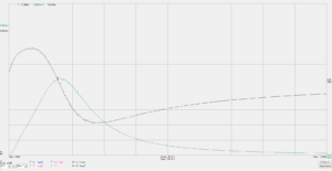
Above is a chart of the measured s11 shunt impedance and two calculated values with 0.2pF of shunt capacitance subtracted and added. Note the effect on maximum R, and the self resonant frequency (SRF) (where X passes through zero).
From this information, we can calculate that the inductor at resonance is represented by some inductance with some series resistance, and Cse=1.5pF. So it is very easy for untidy fixtures, long connections etc to disturb the thing being measured.
BTW, for this DUT that is high impedance around resonance, 6mm of 200Ω transmission line (connecting wires?) has an equivalent Cse if about 0.2pF.
A rule to consider
A good measurement technician challenges his measurements, the fixtures, the instrument etc.
A guide I often give people is this:
if you reduce the length of connections and measure a significant difference, then:
- they were too long; and
- they may still be too long.
Iterate until you cannot measure a significant difference.
A challenge to your knowledge
Q: what is the formula for the resonant frequency of a parallel resonant circuit?
What you answer simply \(f=\frac1{2 \pi \sqrt{L C}}\) ?
Practical inductors also have an equivalent series R, and that is not included above… so it is a formula for ideal components, not for the real world.
A: that is the correct formula for a series resonant circuit, no matter how much series R is involved, and it is a good approximation for parallel resonant circuits with high Q, but has significant error for slow Q values (eg single digit.)
Why do I mention this?
Well, ferrite cored inductors may well have Q in the single digit domain, particularly broadband common mode chokes in the region of their SRF.


