Recent articles discussed the use of e-delay to approximately compensate for cables connecting the DUT to the reference planes.
NanoVNA has had provision for an e-delay compensation for some time, it is a single value that is used to correct the s11 and s21 measurements.
It is very commonly the case that the optimal e-delay values for s11 and s21 compensation are different, so one needed to save a .s2p file for each of the two values and then merge the s11 measurements from its file with the s21 measurements from its file. The requires some work and risk of error.
I recently suggested to DisLord that provision be made in his NanoVNA firmware for specification of separate e-delay values for s11 and s21. He took the suggestion up and with days delivered a beta version with that facility.
This article documents an example use of the facility.
In this article, unless stated otherwise, reference to |s11| and ReturnLoss are to those quantities expressed in dB. Note that |s11|=‑40dB is less than |s11|=‑20dB. ReturnLoss and |s11| are related, ReturnLoss=‑|s11|.
Loss terms used are as defined at Measurement of various loss quantities with a VNA.
The NanoVNA calibration
The NanoVNA was SOLTI calibrated with the SOL parts on the Port 1 jack, and a ~150mm RG316 cable from Port 1 to Port 2 jacks for the T calibration.
The propagation delay of the RG316 cable was measured to be 795ps.
DUT
The DUT is a budget A/B coax switch with UHF jacks.
Test fixture
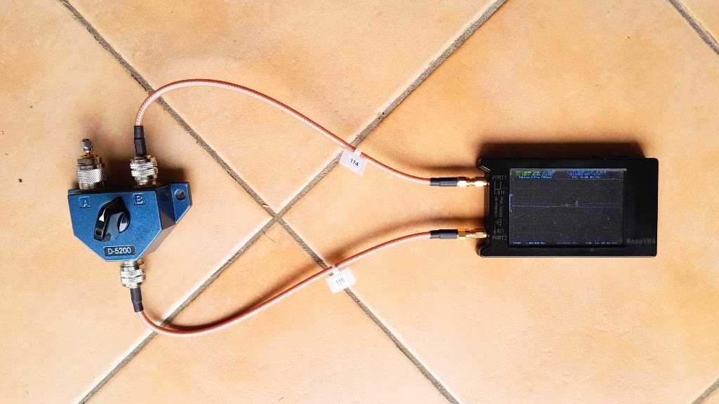
Two identical SMA(M) to UHF(M) RG400 cables were used to connect:
- VNA Port 1 to switch port B.
- VNA Port 2 to switch common port.
A good load (SMA(M) 50R with SMA(F)-UHF(M) adapter) was connected to switch port A.
e-delay calcs
The two RG400 cables are identical to the mm, their one-way delay was measured at 1.5ns.
As mentioned, the cable used for THRU calibration has a propagation delay of 0.795ns and since it is not part of the test jig, it must be deducted.
So e-delay for:
- s11=2*1.5=3.0ns (ie the two way delay on the Port 1 cable); and
- s21=1.5+1.5-0.795=2.205ns (ie delay on Port 1 cable + Port 2 cable less the missing cal cable).
Measurements
Switched through, insertion measurements
Insertion measurements of interest are InsertionReturnLoss and InsertionLoss. Neither of these are directly displayed but are easily calculated and visualised from the display below. The relationships are:
- InsertionReturnLoss=-|s11|; and
- InsertionLoss=-|s21|
VSWR can be calculated from ReturnLoss though it could be displayed directly for users not comfortable with ReturnLoss.
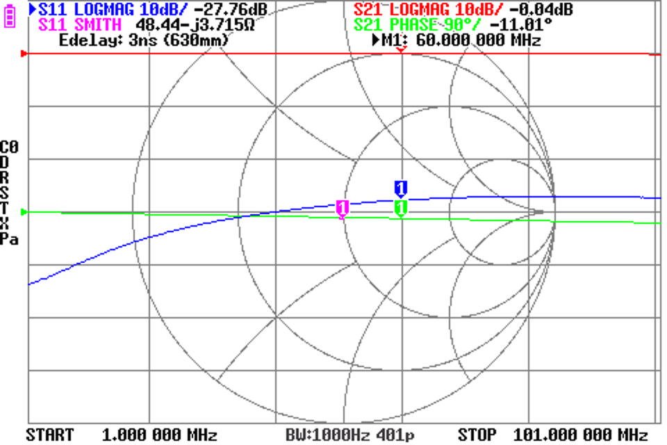
Above is a screenshot. Note the s11 trace is selected so the e-delay displayed is that for s11 compensation. Note that it is the two way propagation time, and the two way distance that is calculated.
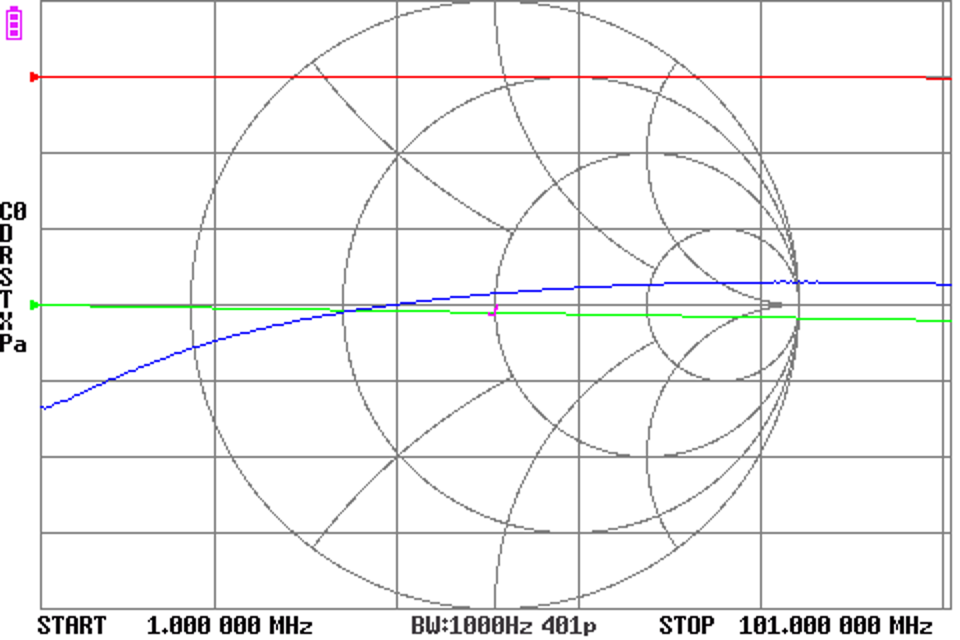
Above is the same chart with markers disable, the Smith chart trace is not obscured by the marker.
Switched to other port, isolation measurement
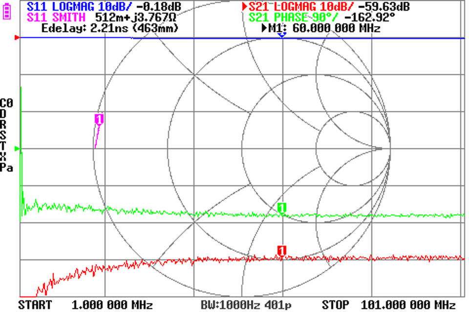
Above is a screenshot. Note the s21 trace is selected so the e-delay displayed is that for s21 compensation. Note that it is the two way propagation time, and the two way distance that is calculated.
It can be seen that this switch ‘grounds’ the unused port.
Deeper analysis
Since we can save a single phase corrected .s2p file, we can run it through a standardised script to deeper analysis.
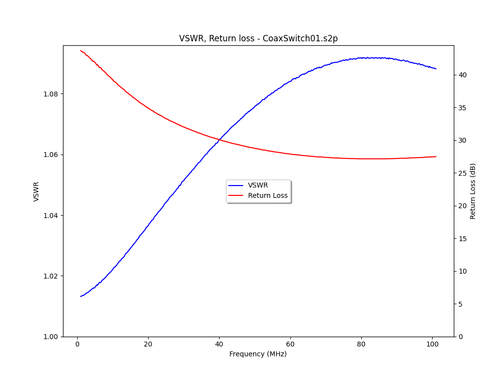
Above is a plot of ReturnLoss and InsertionVSWR. These are ok up to 30MHz, a bit poorer above that… but heh, this uses UHF connectors!
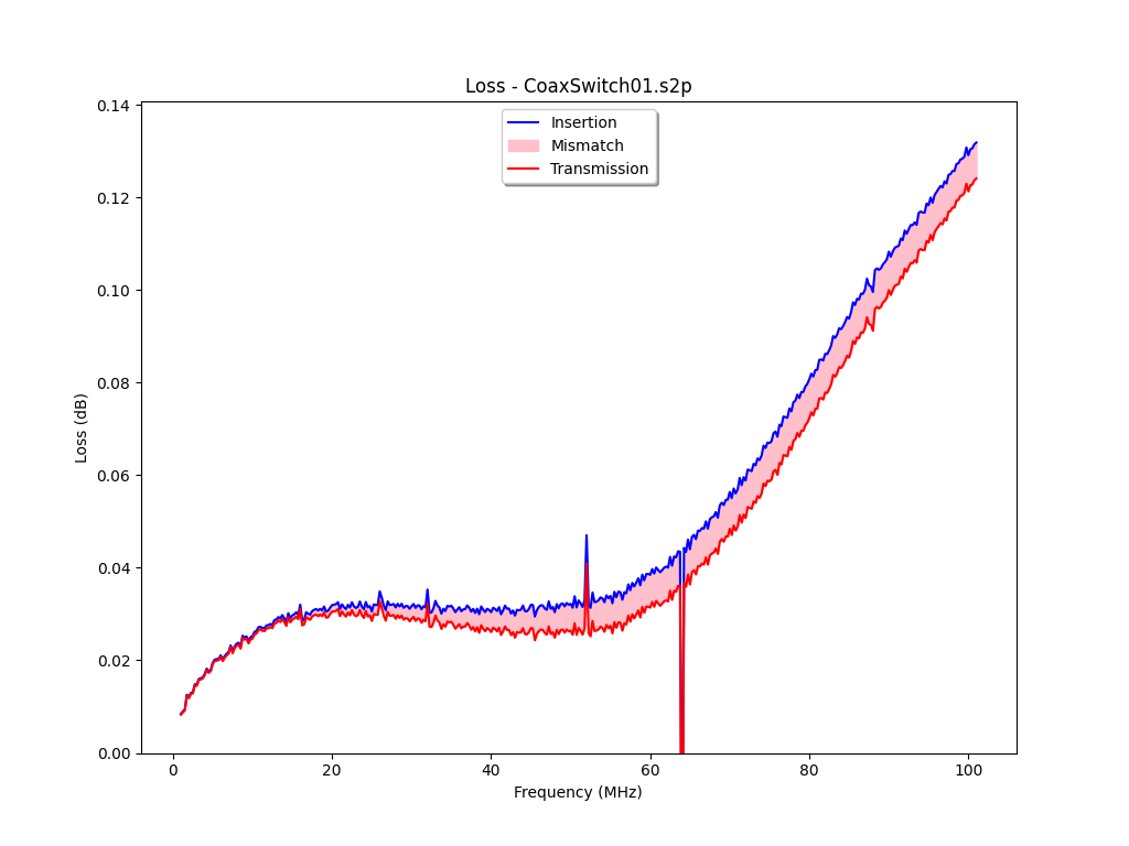
Above is a chart that disaggregates InsertionLoss into Loss or Transmission Loss (which directly gives rise to heat) and MismatchLoss. Note that since the e-delay method compensates delay of the fixture cables but not their attenuation, the chart above captures loss of the fixture cables as well as DUT.
Nothing too surprising here… other than a switch that cost around $30 in 1980 performs quite well up to 60MHz.
Conclusions
Use of e-delay provides a useful approximate compensation for short low loss interconnects used in a test fixture. Provision for separately specified e-dealy for the Port 1 and Port 2 cables provides utility of compensated s11 and s21 measurement in one sweep, one .s2p file.
This facility is now incorporated in Ho-Ro’s builds at https://github.com/Ho-Ro/NanoVNA-D/tree/current-bin-hex.