This article presents measurements of an EFHW antenna system using the transformer design worked up at 1:49 EFHW transformer using a Jaycar LO1238 core – design workup and bench measurements at 1:49 EFHW transformer using a Jaycar LO1238 core – measurement of losses.
The antenna system
Let’s take a system view, component views including bench measurements as reference above are important in qualifying components (eg acceptable Loss), but at the end of the day, the system view is very important. Whilst this section gives a VSWR perspective, it does that in the context of qualified system components.
In this article the antenna system comprises 11m of RG58A/U cable, the transformer described above and 20m of ‘radiator’ wire. This configuration should have a fundamental resonance around 7MHz and support harmonic operation at around 14, 21, and 28MHz.
Note that these type of antenna systems exhibit some amount of inharmonicity, ie the higher modes are not exact integer multiples of the fundamental resonance, there are contributions from both the ‘radiator’ wire, ‘counterpoise’ system and transformer.
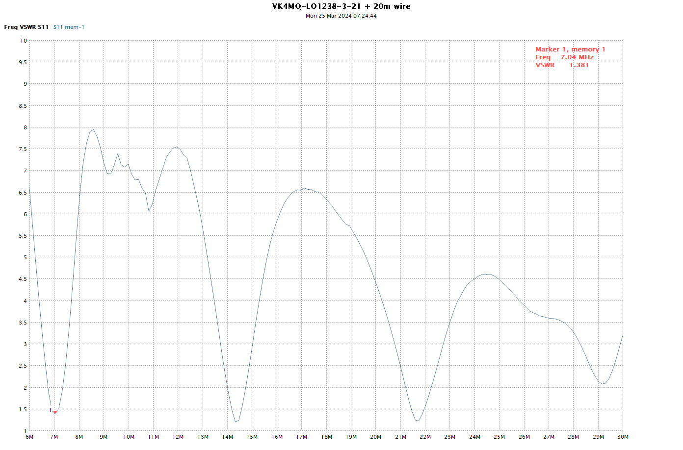
Above is the VSWR plot looking into 11m of RG58A/U cable. The VSWR at the transformer jack point will be marginally higher, but this plot is typical of what might be presented to a transceiver.
The VSWR in the 7, 14, and 21MHz ham bands might well be usable without an ATU with many transceivers, and is well within range of the internal ATU of most modern transceivers for maximised / optimised power output.
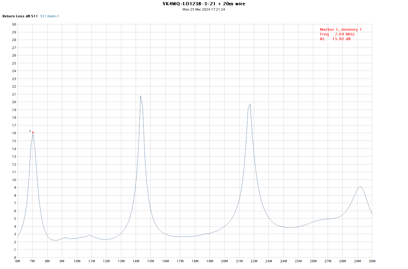
The same scan expressed as ReturnLoss.
VK4MQ’s intended application of this antenna system is for portable / field operation where a wire can be rigged into a tall tree and the transformer used to adapt it to a radio mounted in a vehicle or caravan, or a standalone portable radio with battery such as the Codan 6924 “lunch box radio”.