Small transmitting loop review

I saw a recent ‘maker’ video describing a small transmitting loop for 40m.

The loop used a 3m length of 19mm copper pipe formed into a circle, and at the gap where the ends almost meet, a tuning capacitance is synthesised using coaxial cable.

Screenshot - 15_02_2014 , 12_06_57

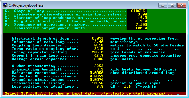
Above is a screen shot from Reg Edwards loop design program. It calculates the radiation resistance at 0.005Ω, loss resistance of the loop at 0.035Ω, capacitance to resonate it of 206pF (Xc=108Ω), and a bandwidth of 3.2kHz.

Continue reading Small transmitting loop review

ATU voltage verification

I described a method for designing antenna systems to avoid excessive voltages in baluns and ATUs at (Duffy 2011) .

This article reports post implementation measurements of an antenna system designed using that method and using a G5RV Inverted V with tuned feeder and ATR-30 ATU with integral 1:1 current balun. The tuned feeder is a home-made line section of 2mm diameter copper conductors spaced 50mm, and 9m in length. An additional 0.5m of 135Ω line connects from the antenna entrance panel to the ATU.

Continue reading ATU voltage verification

A look at internal losses in a typical ATU

This article explores the loss that may be encountered in an ATU in a practical setting.

The load is a G5RV with tuned feeders operating at 3.6MHz. The tuned feeder is 9m of open wire line of characteristic impedance 450Ω, and the impedance seen by the ATU is around 40-j150Ω, this is not a particularly onerous load.

MFJ949E02

Continue reading A look at internal losses in a typical ATU

An inexpensive medium power tuner current balun for HF using Jaycar parts

This is a project to design and build a Guanella 1:1 (current) balun suited for up to 100W on HF with wire antennas and an ATU.

For use with a tuner, the most important design criteria are:

  • high voltage withstand;
  • high common mode impedance;
  • power handling.

Continue reading An inexpensive medium power tuner current balun for HF using Jaycar parts

Design / build project: Guanella 1:1 ‘tuner balun for HF’ – #3

Third part in the series..


Common mode current measurement

Direct measurement of common mode current in an antenna system is the best indicator or whether there is a common mode current problem.

In Common mode current and coaxial feed lines, I mentioned that common mode current is easily measured.

80mIcm

Continue reading Design / build project: Guanella 1:1 ‘tuner balun for HF’ – #3

Design / build project: Guanella 1:1 ‘tuner balun’ for HF – #2

Second part in the series…


Common mode impedance

When baluns are used with open wire feed lines to wire antennas on HF, most commonly the main purpose is to suppress common mode current, to ensure that the current in one wire of the feed line is equal but opposite in direction to the other wire at that point.

Continue reading Design / build project: Guanella 1:1 ‘tuner balun’ for HF – #2

Design / build project: Guanella 1:1 ‘tuner balun’ for HF – #1

This is a project to design and build a Guanella 1:1 (current) balun for use on HF with wire antennas and an ATU.

First part in the series…


For use with a tuner, the most important design criteria are:

  • high voltage withstand;
  • high common mode impedance;
  • generous power handling given our 400W PEP limit, possibly 1kW in the future.

Continue reading Design / build project: Guanella 1:1 ‘tuner balun’ for HF – #1

WIA 4:1 current balun – further explanation

4-101a

I mentioned in my article WIA 4:1 current balun that the use of a single toroidal core in the above graphic compromises the balun. This article gives a simple, but more detailed explanation for the technically minded of why the shared magnetic circuit ruins the thing.

Continue reading WIA 4:1 current balun – further explanation

Cobwebb antenna impedance matching scheme

From time to time, correspondents have asked how the Cobwebb antenna works, and particularly how the impedance matching scheme works.

Firstly, what is the Cobwebb?

It is an innovative antenna for small spaces, quite compact and as I recall originally intended to cover five amateur bands from 20-10m.

Continue reading Cobwebb antenna impedance matching scheme