Using an attenuator for NoiseLo/NoiseHi in NFM

A common method of making Noise Figure measurements of a receiver is to use a noise generator of known noise power. The output power of the DUT is measured with the generator off (NoiseLo) and on (NoiseHi), a Y factor calculated, and from that Noise Figure is calculated.

Continue reading Using an attenuator for NoiseLo/NoiseHi in NFM

Simple Morse beacon keyer updated 2014/03/01

W4HBKgrab001

Above is a clip from W4HBK’s 40m grabber today, the signal is VK2OMD running 5W QRSS6 over a 14,700km path. We can infer (Duffy 2012b) from the 15dB S/N in that capture in 0.25Hz noise bandwidth, that in an 800Hz CW filter for say -5dB S/N (threshold of copy) we need 15dB more signal, or 160W for reliable copy. (Less power may be adequate for very short QSOs at the peak of fade cycles.)

Continue reading Simple Morse beacon keyer updated 2014/03/01

An inexpensive current limiter for flashing and initial testing of ESCs – Mk II

There is a risk of damage when flashing ESCs. It accrues from the fact that ESCs have a three-legged H bridge and if a high and low FET are turned on simultaneously, damaging currents may flow. In fact, this can be an issue if the FETs are on together for just microseconds on each PWM cycle. Loading the wrong hex module is a recipe for disaster, it may turn on FETs in an unexpected way.

So, for safety, the ESC should be powered from a current limited power supply during flashing and initial motor testing.

In a process of continuing development, this article describes a variation on the inexpensive current limiter for flashing and initial testing of ESCs – Mk I.

Continue reading An inexpensive current limiter for flashing and initial testing of ESCs – Mk II

Cooling an IC2200H

IC2000HCooling2

I have an IC2200H mounted on my operating table with 25mm clearance above the radio and ample room for convection currents to assist in heat removal. It is concerning that the case temperature reaches temperatures that are not safe to touch, temperatures in excess of 75° (55° above ambient) have been measured and that has not triggered the internal temperature protection… so it could get hotter still!

Whilst it might take a while for the radio to reach high temperatures, in the long term, it must dissipate around 139W when transmitting on HIGH power setting and at ambient temperatures as high as 35° in the shack. (Rated input is 15A at 13.6V for 65W out, leaving 139W of heat to be dissipated.)

This is one of those high power mobile radios that advertises no fan as an advantage, but it is clearly not up to the task!

The objective of this change is to keep the external parts below 60°, the (ASTM standard C1055  1999) 5 second human skin burn threshold.

Continue reading Cooling an IC2200H

An inexpensive current limiter for flashing and initial testing of ESCs – Mk I

There is a risk of damage when flashing ESCs. It accrues from the fact that ESCs have a three legged H bridge and if a high and low FET are turned on simultaneously, damaging currents may flow. In fact, this can be an issue if the FETs are on together for just microseconds on each PWM cycle. Loading the wrong hex module is a recipe for disaster, it may turn on FETs in an unexpected way.

Continue reading An inexpensive current limiter for flashing and initial testing of ESCs – Mk I

Tricopter build – 20140123

My first tricopter build is based on a frame from Hobbyking. they say:

Designed from the ground-up by our own engineering team, the X900 Tricopter is a culmination of months of design, testing and material sourcing to provide you with the perfect mix of quality, performance and value.

Oh well, with hype like that, the reality can only fall short!

The size is 820mm diagonal between motor shafts (not 900mm as the type suggests).

Key elements of the configuration are:

  • Hobbyking X900 tricopter frame;
  • Turnigy D3530-14 1000kv Brushless Motor;
  • Hobbywing Skywalker 4S 40A ESC, loaded with BLHeli v11.0;
  • HK 11×4.5 SF two blade propellers;
  • Hextronic MultiWii 328P Flight Controller w/FTDI & DSM2 Port;
  • FRSKY V8FR-II HV receiver;
  • Battery monitor;
  • Turnigy Discovery Beeper
  • Zippy 3000mAh 3S 30C LiPo battery;
  • Turnigy 9XR/OpenTx transmitter.

The frame has had its problems.

spring


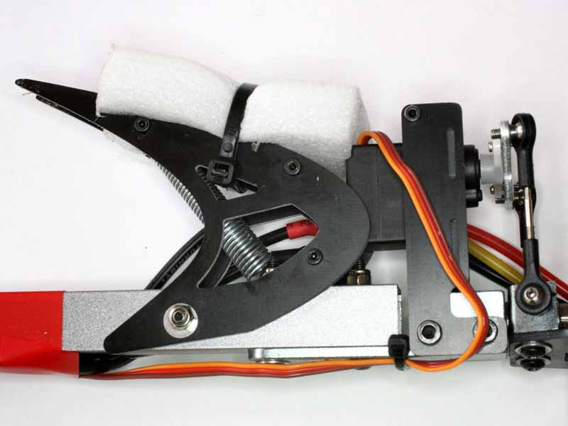
The springs used for the “shock absorbing landing legs” are low grade and straighten out when stretched by the legs, see above. Fundamentally, the leg design is flawed, the spring fouls the recommended tail servo and it fouls the mounting screws at the end of the tricopter arms.

TriFoot

The replaced plated steel springs were placed under the inboard arm mounting nut and washer and onto one of the pins in the leg assembly, see above. They don’t found anything in this configuration. The shock absorbing leg folds up so that the servo bracket etc take the bump when the tricopter lands… the most delicate part of the whole craft is unprotected. A temporary measure is some foam zip tied to the legs, but the whole shock absorbing leg is proving to be a bit of a worthless gimmick.

The kit lacked appropriate screws to fix the servo to its bracket and the servo crank to the ball link crank, in my case some 2mm hex head screws and nuts were used.

The one part of the frame that seems well done is the tail servo bearing and motor support. The system is free of backlash, and control is stable.

The ESCs were unwrapped, cables and JST-1.0mm attached to the C2 pads as permanent programming cables and longer motor wires fitted, re-wrapped and loaded with BLHeli Multi v11.0. The ESC was given a bench test on some challenging motors at 4S, and it was very responsive with no hint of sync problems.

The FC was loaded with Mutliwii 2.3 configured for a tricopter.

Initial flights have been good, the craft has plenty of power on a flat battery, is quite responsive for such long arms, and quite stable though tuning work continues. Expectation is that a 4S battery will allow carrying camera payload should that transpire.

More when it is tuned!

Wire current rating for single FEP (Teflon) or Silicone insulated (200°) conductor in free air (30°).

AWGCond dia (mm)CSA (mm^2)R/km (Ω)Imax
26.533.60.513241
35.826.70.647209
45.221.20.815180
54.616.81.03156
64.113.31.30135
73.710.51.63117
83.38.372.06101
92.96.632.6087.4
102.65.263.2875.6
112.34.174.1365.4
122.13.315.2156.6
131.82.626.5748.9
141.62.088.2942.3
151.51.6510.536.6
161.31.3113.231.7
171.21.0416.627.4
181.00.82321.023.7
190.910.65326.420.5
200.810.51833.317.7
210.720.41042.015.3
220.640.32653.013.3
230.570.25866.811.5
240.510.20584.29.93
250.460.1621068.59
260.410.1291347.43
270.360.1021696.43
280.320.0812135.56
290.290.0642694.81
300.260.0513394.16

Derived in part from data published by Wiremax.