VU3SQM directional wattmeter build – #4

VU3SQM directional wattmeter build – #1 laid out the first steps in design review and build of a directional wattmeter.

At long last, some PTFE rod arrived to permit assembly of the transformers.

For reasons discussed in an earlier article, the transformers use a larger core than the original VU3SQM. They need to stand above the board, and whilst that compromises the mechanical strength of the assembly, it should have better performance. Continue reading VU3SQM directional wattmeter build – #4

W5KV’s transmitting loop measurements – DELUXE HG-1 PreciseLOOP 7MHz

W5KV documented his measurements of a 3m perimeter circular transmitting loop, DELUXE HG-1 PreciseLOOP, 2.0m centre height above ground.

This article explores his 7MHz observations.

Assuming the measurements were made with the antenna clear of disturbing conductors etc, in good condition.

Above is his VSWR scan.

The key measurements were:

  • centre frequency 7.175MHz, VSWRmin=1.1;
  • VSWR=3 bandwidth 36kHz.

Based on that, we can estimate the half power bandwidth to be 30kHz if R is less than Ro, more like 33kHz in the other case, but we will be optimists.

A NEC-4.2 model of the antenna at 14MHz was built and calibrated to the implied half power bandwidth (30kHz). Model assumptions include:

  • ‘average’ ground (σ=0.005, εr=13);
  • Q of the tuning capacitor = 2000;
  • conductivity of the loop conductor adjusted to calibrate the model half power bandwidth to measurement.

Note that the model may depart from the actual test scenario in other ways.

Above is the VSWR scan of the calibrated model, the load is matched at centre frequency and half power bandwidth is taken as the range between ReturnLoss=6.99dB points. Continue reading W5KV’s transmitting loop measurements – DELUXE HG-1 PreciseLOOP 7MHz

Measuring common mode current with a scope

I wrote recently of a flawed test of balance performance of an antenna system and an ATU, and some readers have taken up the issue, basically asking the question “then, how do you measure balance of a two wire line with a scope?”

The first step is that you must define what you mean by “balance”.

For most wire HF antennas, the balance objective should be equal but opposite currents in the adjacent wires at all locations along the line (recalling the currents may vary along the line). This reduces radiation from the feed line (which can cause EMC problems with nearby appliances / systems), and reduces very local noise pickup on receive (from those same appliances / systems).

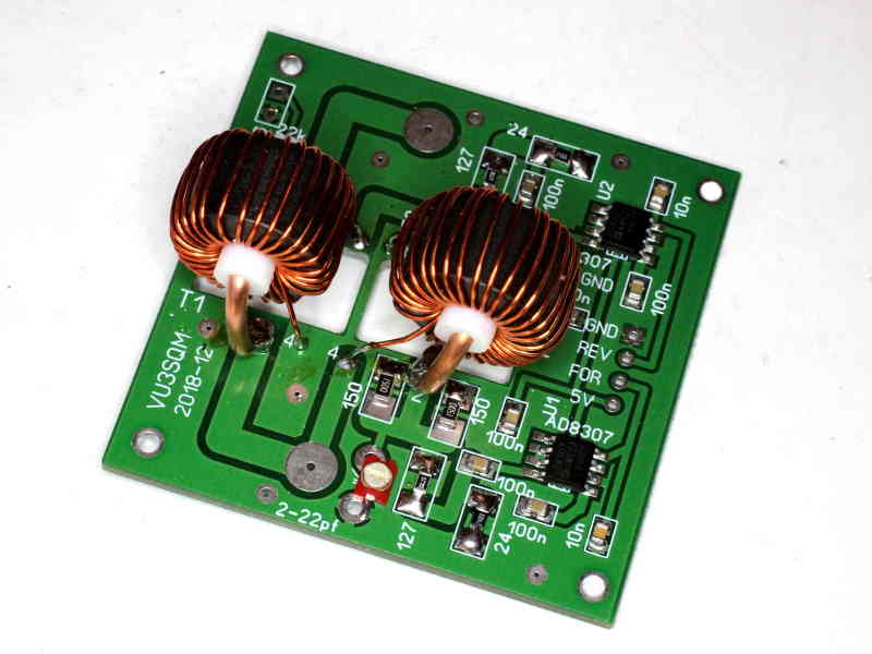
Let’s take KA0KA’s scope display from the reference article, but assume that they were taken from current probes so that we are directly measuring feed line currents rather than voltage. Current probes allow the scope to measure current on a conductor placed through the probe, an RF current probe (or current transformer) can be as simple as a suitable ferrite toroid with the primary conductor passing once through the center of the core, and a secondary winding of 10-30 turns loaded with a low value resistor, and the scope input connected across the resistor.

The obvious measurement method

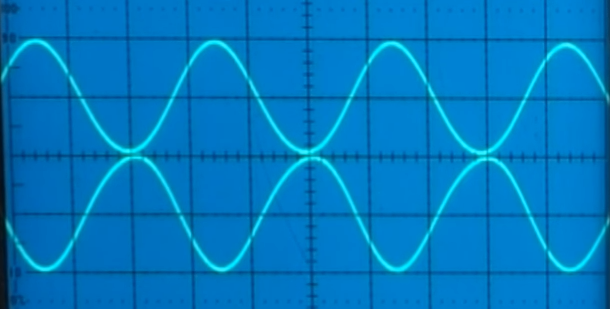
Above, the first measurement shows both channels, and the currents appear almost equal in magnitude and almost opposite in phase, but it does appear that there is a slight phase difference, perhaps 5-15° from exactly opposite phase. Each channel is almost 2div peak to peak, and let’s assume the calibration factor is 1A/div. Continue reading Measuring common mode current with a scope

Australian amateur population trends 1998 – 2018

This is a 2018 update of an article written originally in October 2005, earlier editions published on VK1OD.net which is now offline.

Over recent years to 2002, the number of issued amateur licences was declining, the trend was about 2.8% pa decline over the five years to 2002.

This has concerned some people, who took the view that the decline was a harbinger of the impending demise of Amateur Radio. Continue reading Australian amateur population trends 1998 – 2018