A common mode choke for a VDSL pair – LF1260 core

This article describes a common mode choke intended to reduce RF interference with a VDSL service.

The MDF is located where the underground cable enters the building. From here it rises vertically and travels some 25m across the ceiling to the VDSL modem. Continue reading A common mode choke for a VDSL pair – LF1260 core

nanoVNA-H – measuring an inductor – is it a no-brainer?

Let’s explore measurement of a test inductor with the nanovna.

Above is the test inductor, enamelled wire on an acrylic tube.

An online expert’s advice make this task look like a no-brainer:

For a 100 nH inductor you are probably using an air wound coil so you won’t see that much change in inductance with frequency. However, inductors made with toroids will because the permeability of the core goes down with frequency.

So, this is an air cored inductor, permeability is approximately that of free space, a constant 4πe-7 independent of frequency. Nevertheless we will see that apparent inductance can change with frequency. Continue reading nanoVNA-H – measuring an inductor – is it a no-brainer?

nanoVNA-H – continuing USB-C repair

I have reported issue with the USB-C plug / socket arrangement on the nanoVNA-H.

It is very sensitive to any jiggling of the cable or connector, causing a reset of the nanoVNA which almost always means lost work. The supplied cable was a partial cause, but sadly the jack on the PCB is also faulty.

This has progressively gotten worse to the point the nanoVNA-H is unusable. I have had a replacement socket on order for months from China where public health problems are causing chaos, it has only just shipped so could be some months yet.

I do realise that this is replacing cheap Chinese junk with cheap Chinese junk.

Anyway… it finally arrived after many months. A pack of 10 sockets cost $2.30 incl shipping, so it gives one a fair idea of how cheap the low grade connector that was used would have come.

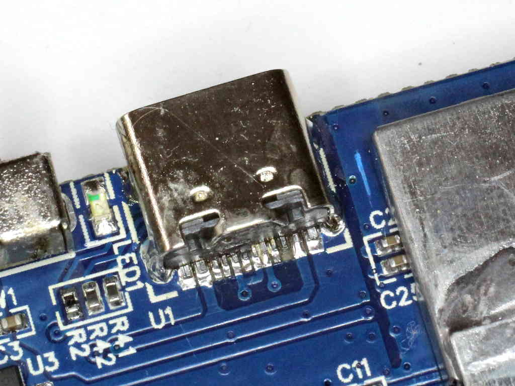
Above, the replacement USB-C socket soldered in to the board without removing the display. The SB1 pad lifted of the board during removal of the old socket, no connection is made to it, so no harm done. Continue reading nanoVNA-H – continuing USB-C repair

NEC – vertical monopole ground wave study

The article NEC – vertical monopole radiation resistance study discussed ‘radiation’ in the strict sense, this article takes a look at ground wave propagation from the same antenna.

NEC insight

Let us look at an example of a quarter wave monopole with 120 shallow buried radials, soil σ=0.005  εr=13, average ground, at 3.8MHz.


Above is the model geometry. Continue reading NEC – vertical monopole ground wave study

NEC – vertical monopole radiation resistance study

A recent online discussion contained an analysis of the radiation efficiency of a vertical monopole over real ground.

The poster dismissed the values calculated by 4NEC2 and proposed his own formula \(RadiationEfficiency=\frac{35.6}{\mathbb{R}Z_f}\) where 35.6 is the radiation resistance Rr of a quarter wave monopole over a perfectly conducting earth (PCE).

The reasoning seems to depend on Rr being independent of the ground type, but that is quite flawed.

NEC insight

Let us look at an example of a quarter wave monopole with 120 shallow buried radials, average ground, at 3.8MHz.


Above is the model geometry. Continue reading NEC – vertical monopole radiation resistance study

4NEC2 – summary statistics discussion

I am a frequent user of 4NEC2 despite its many defects. It is a great work of software, in need of improvement that I suspect will never happen. Its author explained some time ago that it was developed in VB6 and with Windows upgrades, he no longer has a working VB6 development platform.

So, despite its defects, it is a very useful tool.

This article set about explaining interpretation of the summary statistics shown on 4NEC2’s main form.

I will sometimes substitute _ for – in some 4NEC2 quantity labels for clarity in mathematical expressions. Continue reading 4NEC2 – summary statistics discussion

FT240-43 matching transformer for an EFHW – NEC model at 3.6MHz

The article End Fed Half Wave matching transformer – 80-20m laid out a design for a EFHW transformer based on the readily available FT240-43.

This article builds an NEC model for an EFHW antenna at 3.6MHz incorporating a realistic model of the above transformer.

NEC provides for a NT card characterising a two port network using Y parameters.

Y parameter model for the transformer

The Y parameter model is based on measured input impedance with port 2 open circuit, and short circuit, and the observed turns ratio.

Impedance was measured with the transformer at 3.6MHz using an AA-600.

Above, the calculated Y parameter model including a prototype NT card. This model captures the various loss components of the transformer, mainly magnetising loss, at 3.6MHz. Continue reading FT240-43 matching transformer for an EFHW – NEC model at 3.6MHz

Small efficient matching transformer for an EFHW – NEC model at 3.6MHz

The article Small efficient matching transformer for an EFHW laid out a design for a small EFHW transformer.

This article builds an NEC model for an EFHW antenna at 3.6MHz incorporating a realistic model of the above transformer.

NEC provides for a NT card characterising a two port network using Y parameters.

Y parameter model for the transformer

The Y parameter model is based on measured input impedance with port 2 open circuit, and short circuit, and the observed turns ratio.

Impedance was measured with the uncompensated transformer at 3.6MHz using an AA-600, the compensation in the reference article has little effect at 3.6MHz.

Above, the calculated Y parameter model including a prototype NT card. This model captures the various loss components of the transformer, mainly magnetising loss, at 3.6MHz. Continue reading Small efficient matching transformer for an EFHW – NEC model at 3.6MHz

Exploration of feasibility of ground wave comms on 80m VK2OMD-VK1EA

This article is a desk study of the likelihood of ground wave communications over the path VK2OMD-VK1EA, about 150km.

To be useful, S/N needs to exceed 10dB.

Ham mythology has it that ground wave is good for 100km on 80m without much qualification.

Ambient noise

Ambient noise is very important, it is one factor of the Signal / Noise ratio which sets the limit for communication.

Using ITU-R P.368-9 we find that expected median noise figure in a residential precinct at 3.6MHz is 57dB. Continue reading Exploration of feasibility of ground wave comms on 80m VK2OMD-VK1EA

LDF4-50A shield prep with simple hand tools

Commscope makes a range of prep tools that have good productivity but are quite expensive for the hobbyist.

There are different forms of connectors for LDF4-50A, this article discusses a modern type that uses a collet to clamp the cable to the connector body.

There are many ways to prepare the shield end. This article describes one using a fine tooth pull saw which makes for good results for a novice.

Above, an Excel thin kerf razor saw #55001 which has a K5 handle and 30490 46tpi pull saw (~$20 on eBay).

Above, a 3.6mm (0.14″) zip tie is pulled quite firmly into the valley of the corrugated shield to serve as a saw guide. Note the partial cut. The width of the zip tie is critical, and this width is common. The objective is to trim the shield just a little towards the end from the middle of the crest. (Normally you might have the jacket trimmed further back to accommodate the o ring and back of the connector, but it can be trimmed when the cut is complete.) Continue reading LDF4-50A shield prep with simple hand tools