Diagnosis of a 9:1 transformer from NanoVNA plot

A chap recently posted online a question:

I have added two 1:9 transformer (2T/6T) back to back (high side together) and measured with the nanovna – 2 port measurement, as the binocular core I am not confident BN73 or not.

Also I swiped with one port S11, with one transformer where the high side is terminated with a 470ohm resistor load.

Please advise if it can be used for beverage antenna for 160/80m.

Let’s focus on the second test, and assume that the measurements are valid (and that is often an issue), that the 470Ω resistor is close enough to 450+j0Ω and the connections are short.

Above is his s11 sweep from 1 .5-7MHz.

I suspect this is actually #43 material. Continue reading Diagnosis of a 9:1 transformer from NanoVNA plot

Digital display for DIY 25W dummy load – part 4

Digital display for DIY 25W dummy load – part 1 described a  digital display for a DIY 25W dummy load / digital wattmeter. The original research tested implementations on an Arduino Nano (ATmega328P) and Arduino Mini Zero (ATSAMD21). Though the Zero appears the better chip (32bits, better ADC resolution etc), the dev board is so noisy (ADC wise) that the Nano produces better results.

Other candidate chips are those of the newer AVR chips, and to that end some ATtiny1614 chips were purchased for trial. Unfortunately I have not seen inexpensive dev boards and the chips are not available in DIP format, these are SOIC14 (SSOP14) 150mils.

Above is the result of this morning’s cooking… three ATtiny1614 chips on DIP style break out boards for prototyping. The chips were soldered in a T962 IR reflow oven. The very long unmasked sections of pad to accommodate different width chips make for a messy looking solder job as the solder runs along the long pads. Continue reading Digital display for DIY 25W dummy load – part 4

dB loss is always negative… right???

A recent online posting set out to inform the masses:

The concept of free space path loss (FSPL) is widely misunderstood. Some university lectures and even texts get it wrong. …

The result is some dB of loss which is the ratio of the power received to the power transmitted expressed in dB form.

Errr no! Continue reading dB loss is always negative… right???

Digital display for DIY 25W dummy load – part 3

Digital display for DIY 25W dummy load – part 1 described a  digital display for a DIY 25W dummy load / digital wattmeter. The original research tested implementations on an Arduino Nano (ATmega328P) and Arduino Mini Zero (ATSAMD21). Though the Zero appears the better chip (32bits, better ADC resolution etc), the dev board is so noisy (ADC wise) that the Nano produces better results.

This article documents tests on three other dev board alternatives:

  • Arduino Nano Every (genuine);
  • Wemos SAMD21G board; and
  • Seeed XIAO mini Zero.

Baseline: Arduino Nano v3.0 (clone)

Above is the initial prototype Arduino Nano v3.0 (16MHz ATmega328P) with OLED display. This clone has a CP210x serial chip, clones with a claimed FTDI chip are probably fakes, ones with CH340x chips are probably ok. Continue reading Digital display for DIY 25W dummy load – part 3

FT37-43 for a 49:1 EFHW transformer enquiry

A correspondent asked whether Sontheimer coupler – transformer issues – an alternative design – FT37-43 could be used to inform design of a 49:1 EFHW transformer based on the same core, but with a 2 or 3t primary.

In the case of the Sontheimer coupler the winding with the higher number of turns appears in shunt with the nominal 50Ω load, and its effect on InsertionVSWR and the core loss can be predicted reasonably well and confirmed by measurements as in the referenced article.

In that instance, a 7t winding in shunt with the nominal 50Ω load causes excessive core heating, a 3t winding will be worse, and 2t worse again.

The case of an EFHW transformer is somewhat similar, the difference is now that the winding with less turns in approximately in shunt with the nominal 50Ω primary referred load. The same Simsmith model can be used to predict likely InsertionVSWR due to primary magnetising admittance, and the core loss.

Let’s try the 3t case first, with the experience of the referenced article we can expect it will have insufficient turns for good performance.

Above is the Simsmith model of a Fair-rite 5943000201 core (equivalent dimensions to FT37-43) with a 3t winding. Note this does not apply to Amidon #43 as their material is significantly different in characteristic. Continue reading FT37-43 for a 49:1 EFHW transformer enquiry

(tr)uSDX firmware, bootloader, application – an explanation

Introduction

The term firmware means lots of things to lots of people, and you will see so many definitions that it becomes confusing.

It is apparent from postings by people about (tr)uSDX (trusdx) that the rubbery definition prevails in that environment also.

The term firmware came into being 50 odd years ago, about the time that microcomputers appeared. There was a need for a term to describe something that sat between traditional hardware and software, the programming that was ’embedded’ in the system.

ATmega328P memory

In the case of the ATmega328P (as used in the (tr)uSDX), it contains three main blocks of memory and some auxilliary non-volatile storage, the three main types are:

  • RAM (volatile scratch storage used for running programs);
  • FLASH (non-volatile memory used for user programs (instructions and constant data); and
  • EEPROM (non-volatile memory often used to save settings, calibration data etc).

Firmware

We might reasonably regard that all of the contents of FLASH is firmware.

Bootloader

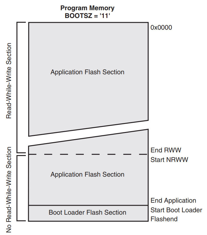
(tr)uSDX uses a bootloader, user code that can be executed on startup to load user programs into FLASH. In the case of the ATmega328P, the bootloader resides in FLASH at the top of the address range. FUSE settings tell the system to start at the boot section on power on reset, and they can be used to protect the bootloader from corruption on reliable systems (this last feature is NOT used on (tr)uSDX).

Above is a map of FLASH memory for an ATmega328P for the configuration used by (tr)uSDX from the chip datasheet. Continue reading (tr)uSDX firmware, bootloader, application – an explanation

(tr)uSDX bootloader corruption – a smoking gun – an experiment

At (tr)uSDX bootloader corruption – a smoking gun I proposed that the (tr)uSDX (trusdx) is vulnerable to users attempting to program the initial bootloader file using the (tr)uSDX USB port and its bootloader interface because without protection, that will attempt to overlay the bootloader while it is being executed and that is likely to corrupt the bootloader.

The (tr)uSDX bootloader code is proprietary, ie secret.

This article documents an experiment that demonstrates the vulnerability, and the effect of bootloader section protection.

Below are a series of verbose AVRDUDE logs of the operations to discover / demonstrate the outcomes. Continue reading (tr)uSDX bootloader corruption – a smoking gun – an experiment

(tr)uSDX bootloader corruption – a smoking gun

A common topic of discussion on (tr)uSDX (trusdx) forum is problems in loading firmware (application or bootloader.

A user posting provides evidence for discussion of the problem in this case, probable cause, solution, and a better design to prevent the problem.

Analysis

The type of programmer (Arduino), connection (COM port) are the settings one would use to talk to a bootloader already installed on the mcu to write the application program to flash. They are not the settings one would use to install the bootloader, they are not suitable for talking to the ISP facility burned into silicon. Continue reading (tr)uSDX bootloader corruption – a smoking gun

Digital display for DIY 25W dummy load – part 2

Digital display for DIY 25W dummy load – part 1 described VK4MQ’s build of a DIY 25W dummy load / digital wattmeter with very good performance. As part of the project, Bruce made an exhaustive set of measurements of Prf vs Vdc from 0.001W to 25W. A second order curve fit was calculated and is used in the instrument to transform measured Vdc to Prf for display.

That project was an elaboration of a design worked up at Digital display for QRP labs 20W dummy load – part 1 and following articles. That workup included an LTSPICE model of the half wave detector with BAT46 diode, 0.1µF capacitor and 56k+1k voltage divider. A second order curve fit was calculated and is used to transform measured Vdc to Prf for display.

This article compares the LTSPICE model data set, its curve fit, the measurements of Bruce’s implementation, and its curve fit. Continue reading Digital display for DIY 25W dummy load – part 2