Riding the RF Gain control – part 4

This article continues on from Riding the RF Gain control – part 3 and explores the operating advice when applied to the next generation of receivers.

Direct sampling SDR

Lets jump a generation to the direct sampling SDR configuration.

In this category, I am covering receivers that do not convert the receive signal to an intermediate frequency, the ADC samples the signal at its off-air frequency.

The receivers may or may not have the following elements ahead of the ADC:

  • preamplifiers;
  • bandpass filters;
  • attenuators.

Because there may be no amplification prior to the ADC in some operating configurations, a voltage controlled attenuator may be used to prevent overflow of the ADC, this is the ‘analogue’ part of the AGC system. Continue reading Riding the RF Gain control – part 4

Riding the RF Gain control – part 3

This article continues on from Riding the RF Gain control – part 2 and explores the operating advice when applied to the next generation of receivers.

Conventional superheterodyne communications receiver with DSP demodulation.

The next generation of receivers was a conventional superheterodyne with a DSP based demodulation stage (initially at quite low Intermediate Frequency to suit the power of the available DSP chips).

Communications receivers were enhanced by replacement of the demodulators with a DSP performing demodulation digitally. The DSP sampled the IF signal and digitised it, and channel filtering and demodulation was performed ‘mathematically’ using the digital data stream as input.

There are two significant differences with this change:

  • receiver bandwidth can be determined by digitally synthesised passband filters in the DSP; and
  • first step in the DSP process is conversion of the IF signal to a digital stream in an analogue to digital converter (ADC).

Critically, the Analogue to Digital Converter (ADC) had an overflow point, and overflow of the ADC creates serious IMD and major degradation of received signal, overflow has to be prevented at all cost. To limit the power delivered to the ADC, a narrow ‘roofing’ filter usually preceded it, and the channel filter was digitally synthesised. Continue reading Riding the RF Gain control – part 3

Riding the RF Gain control – part 2

This article continues on from Riding the RF Gain control – part 1 and explores the operating advice when applied to the next generation of receivers.

Conventional superheterodyne communications receiver designed for SSB telephony.

Move on to the generation of superheterodyne communications receivers that incorporated a demodulator designed for SSB, and an AGC system that protected the receiver intermediate and later stages (including the demodulator) from overload for even very strong signals, and you have a receiver that broadly, worked automatically from the weakest to very strong signals with RF Gain control set to maximum and little need to adjust AF gain.

The AGC system’s most important function is to protect the receiver intermediate and later stages (including the demodulator) from overload. Levelling the AF output is a lesser priority.

These receivers were not perfect, the AGC was derived from the signal, and SSB suppressed carrier does not contain a consistent component from which AGC can be derived, so it is derived from the signal using a pseudo peak detector. The dynamics means that the AGC leaks away between syllables, and there is small overload during the attack time of the next syllable as it charges again, but with appropriate time constants, the distortion is small. (Some commercial HF links solved this problem by transmitting a reduced carrier typically at -26dBc from which AGC was derived.)

These receivers were subject to IMD in the front end, and operating them with no more preamplification than necessary improved handling of strong out of band signals, and in extreme interference cases inserting a front end attenuator improved IMD performance. The working configuration on low HF where external noise dominates the receiver is to improve IMD response even at the expense of Noise Figure.

These receivers were not perfect, but by and large, good implementations worked very well hands off most of the time.

Delayed AGC

AGC reduces gain ahead of the demodulator, typically in both RF and IF stages, and has the effect of increasing the receiver Noise Figure. Increasing Noise Figure degrades S/N ratio at the receiver output.

The diagram above from (Terman 1955) illustrates the behaviour for AVC, the term that was used with AM receivers at the time and superseded by AGC for SSB receivers. Continue reading Riding the RF Gain control – part 2

Riding the RF Gain control – part 1

Every so often one sees advice from experts on how to operate a communications receiver or transceiver for SSB reception on the HF bands.

Very often that advice is to adjust AF Gain to max, and adjust RF Gain for a comfortable listening level. This is argued today to deliver the best S/N ratio, partly due to delivering the lowest distortion due to IMD in the receiver front end.

The downside of this is that it has prevented normal AGC operation, so the operator must continuously adjust the RF Gain to compensate for fading etc, and the settings may be quite different for each station in a n-way QSO.

I cannot recall ever seeing quantitative support for the claimed improvement in  S/N or ‘quality’, so it seems that it is based on subjective assessment and there may not be quantitative evidence.

Now I was taught this method by my mentor 50+ years ago to operate a receiver he had loaned me… and it DID work in the specific case. It worth exploring why it did work, since this may be the root of the advice that is offered generally, whether appropriate or not.

Further articles will critically examine the advice applied to newer technologies.

Once upon a time…

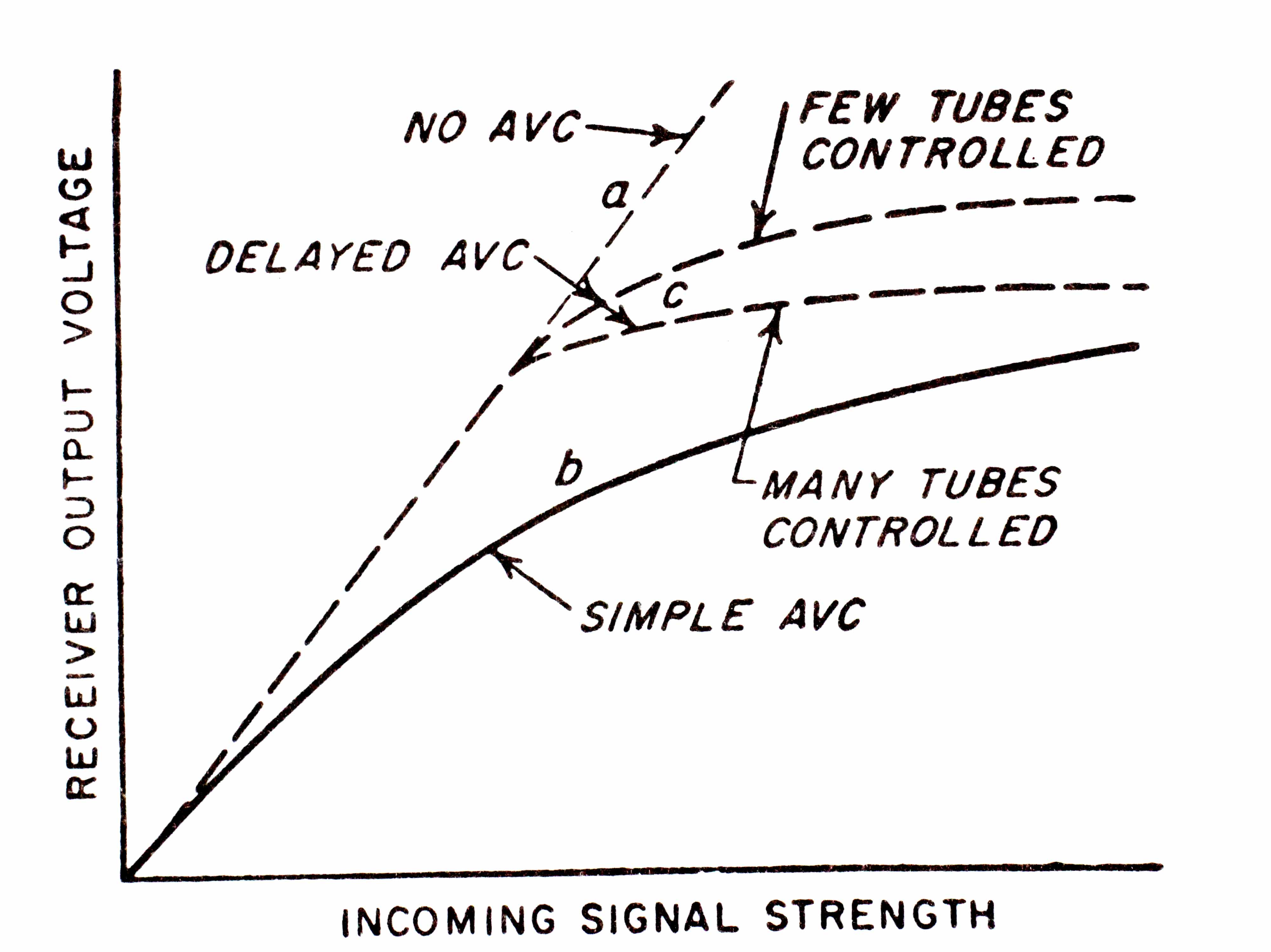
There was a time when receivers had AGC systems that performed poorly, most commonly because they used an envelope detector with BFO injection for SSB and CW reception, and had AGC time constants quite unsuited to SSB Telephony.

In fact, my mentor’s instruction was for such a receiver, an AR8 receiver of WWII vintage which was essentially an AM receiver (including MCW) with BFO for A1 Morse code (CW) reception, that was its intended purpose. The AGC characteristic was tolerable for AM and MCW, and less suited to CW, but quite usable on mid range signals.

It could also receive SSB Telephony using the BFO, but BFO injection level was not adjustable and insufficient for strong signals so it was necessary to reduce RF Gain on strong signals to ensure reasonably good demodulation. The same was required for strong CW signals.

So, the instruction to set AF Gain to maximum and adjust RF Gain to comfortable listening level was a circumvention for the deficient means of demodulation of SSB Telephony, and poorly performing AGC system.

Next part

In the next part, we will explore a basic ‘conventional’ superheterodyne receiver with demodulator designed for SSB telephony.

Common mode choke for DSL line

Having decided to sack iiNet broadband because of recurrent under performance, I need to change VDSL2 modem as the one they supplied was locked to their SIP server (despite their assurances that there was no equipment lock-in).

I replaced it with a TP-Link Archer VR200v which seems to work ok except it is susceptible to disruption when I transmit on HF. The disruption is severe, it causes the VDSL2 modem to disconnect, and it takes around 5 minutes to reconnect.

Several different common mode chokes were tried, all of measured performance, and they all worked in that they eliminated the disconnection problem though they all resulted in small but acceptable uncorrected upstream errors. (Upstream errors are interesting since the upstream modem is 1000m distant.)

The ‘final’ design was chose as the core was just large enough to wind ordinary 4W modular cable through it. So the choke comprises a 2m length of 4W flat modular cable, one end wound 6 turns through a Fair-rite 2643102002 (FB43-1020) suppression sleeve, and RJ12 connectors crunched on in straight through pin wiring (ie reverse the plugs). I found the line jack in the modem would not accept RJ11 (4P4C) plugs readily (common with RJ45 sockets), it required an RJ12 plug. Continue reading Common mode choke for DSL line

Vacuum capacitors – construction implications for SRF

Vacuum capacitors are used for high end applications that require high voltage withstand and low loss.

Though they are called capacitors, and simple analyses treat them as a capacitance with some small equivalent series resistance (ESR), there is more to it.

Above is a view (courtesy of N4MQ) looking into one side of a vacuum capacitor. It consists of an outer cup, and a series of 5 inner cups progressively smaller in diameter. The other side of the capacitor has a similar structure but the cups site in the middle of the spaces between cups in the first side.
Continue reading Vacuum capacitors – construction implications for SRF

Vacuum capacitors – construction implications for Q

Vacuum capacitors are used for high end applications that require high voltage withstand and low loss.

Though they are called capacitors, and simple analyses treat them as a capacitance with some small equivalent series resistance (ESR), there is more to it.

Above is a view (courtesy of N4MQ) looking into one side of a vacuum capacitor. It consists of an outer cup, and a series of 5 inner cups progressively smaller in diameter. The other side of the capacitor has a similar structure but the cups site in the middle of the spaces between cups in the first side.
Continue reading Vacuum capacitors – construction implications for Q

Baofeng charger DC-DC converter

One of the insane things about some Baofeng hand held radios is that the charger cradle requires 10V DC, and malfunctions on car battery voltage.

The cigarette light adapter that came with a Baofeng GT-3TP was simply a pass through device and the charger did not work properly using the adapter plugged into a car.

The charger cradle electronics should include electronics to charge properly from a car, preferably from 10-16V. The implementation is a half-baked idea.

To solve the problem I have made an adapter cable using a small buck DC-DC converter off eBay (~$2), the converter is adjusted to 10V out.

I have used an Anderson Power Pole connector to suit my power distribution, you could use a cigarette lighter plug or some other plug to suit your needs. The output connector is a 2.5mm DC plug. Continue reading Baofeng charger DC-DC converter