This article reconciles measurements with path predictions for a MW AM transmitter on 576kHz. The techniques used could be used to validate / assess the performance of a transmitter.
Source
The source is a MF AM transmitter on 576kHz located about 74km distant.
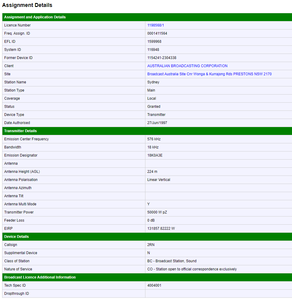
Above is the station data from the ACMA licence register. Conveniently it gives the EIRP as 132kW, we would expect something a little less than 150kW from the nominal 50kW transmitter, system efficiency calculates to 80%.
The EIRP would have been calculated from a set of field strength measurements at the time of commissioning.
Receiver
The receiver comprises a small untuned loop and TinySA Ultra hand held spectrum analyser.
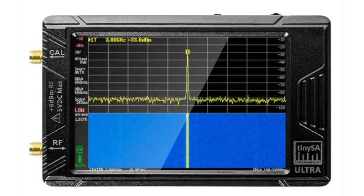
Above, the TinySA Ultra.
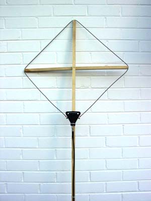
The antenna is a Small untuned single turn square loop for field strength measurements.
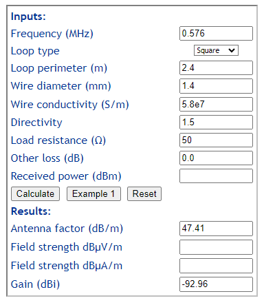
Above is a calculation of the Antenna Factor of the loop antenna.
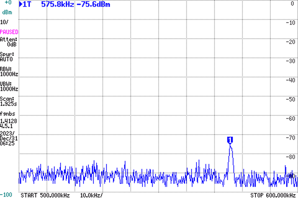
Above, received power is -75.6dBm.
Path
The path is a ground wave path of ~74km over unknown ground. Path loss will include free space path loss and an additional component of ground wave attenuation.
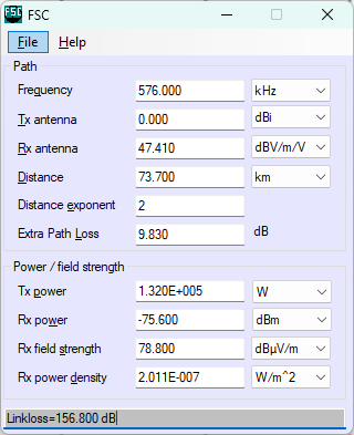
Above, a free space propagation model is calculated with Extra Path Loss added to calibrate the Rx power to measured.
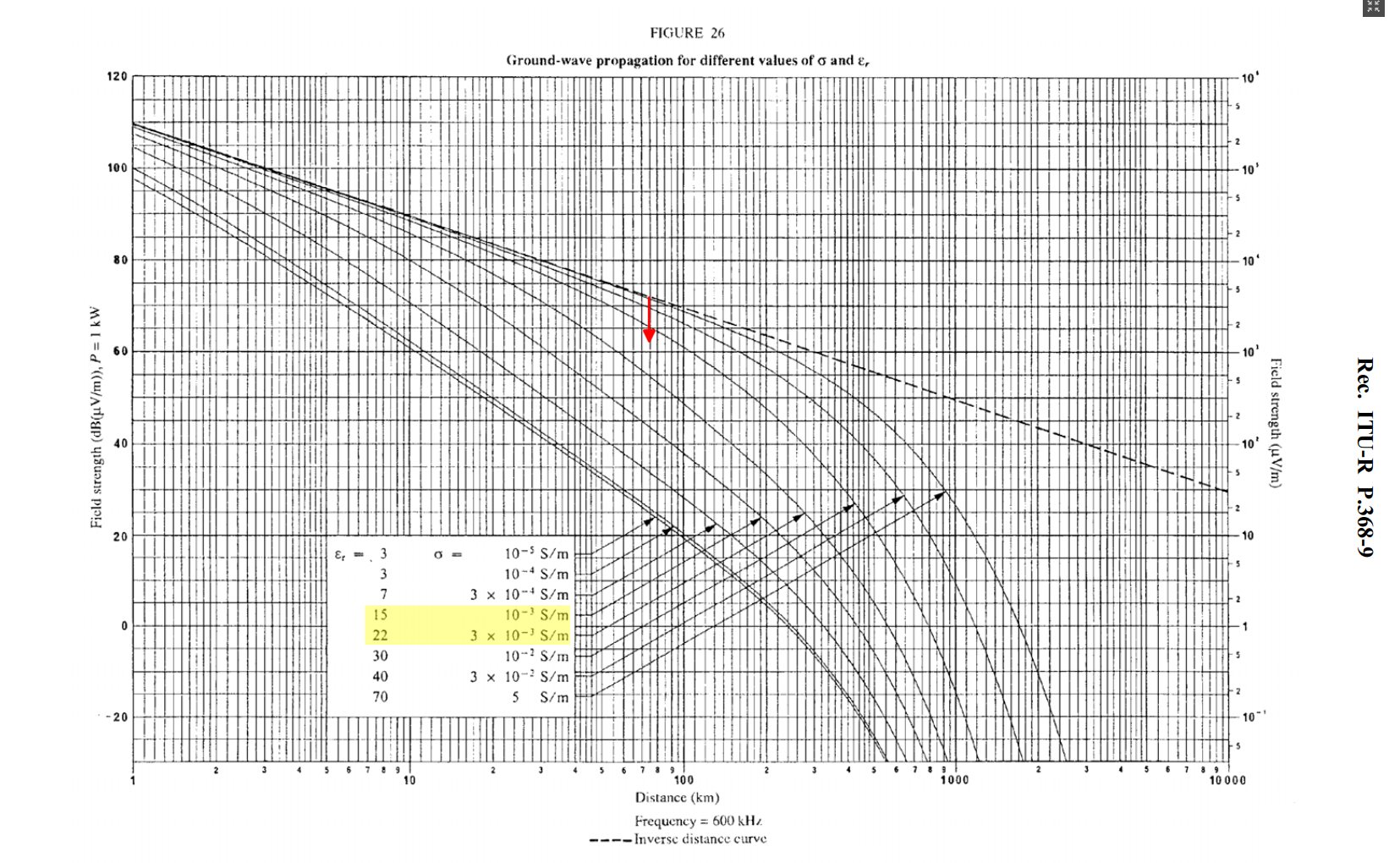
Above is a chart from ITU-R P.368-9 showing the expected ground wave propagation of a vertical wave at 600kHz for different soil types. The red arrow shows the effect of the extra 9.83dB path loss, which suggests average soil characteristics over the path to be in the region of the yellow highlight. It is quite believable, it reconciles well.
Other options
The received power could be measured with a broadband power meter if the source is much stronger than all other signals. That may well suite measurement very close to a transmitter.