I have been asked about compatibility of the RFPM2 current probe with the TinySA and variants.
The current probe was intended for use with a broadband 50Ω RF power meter, but could also be used with a Spectrum Analyser with 50Ω input or an oscilloscope with 50Ω input.
RFPM2 – current probe described a current probe for use with a power meter calibrated in dBm (eg RFPM1 and RFPM2). RFPM2 – current probe – #2 exposed some of the build details. RFPM2 – current probe – #3 showed the implementation.
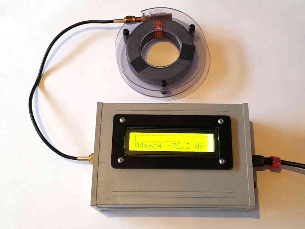
Above the current probe with RFPM2. Whilst this is not of a clamp-on design, the aperture in the core is sufficient to pass a DIN 7/16 connector through.
A test was conducted with the current probe on my TinySA Ultra.
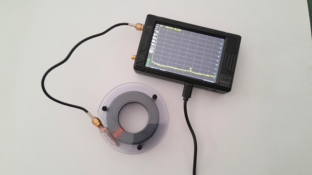
Above, the test configuration.
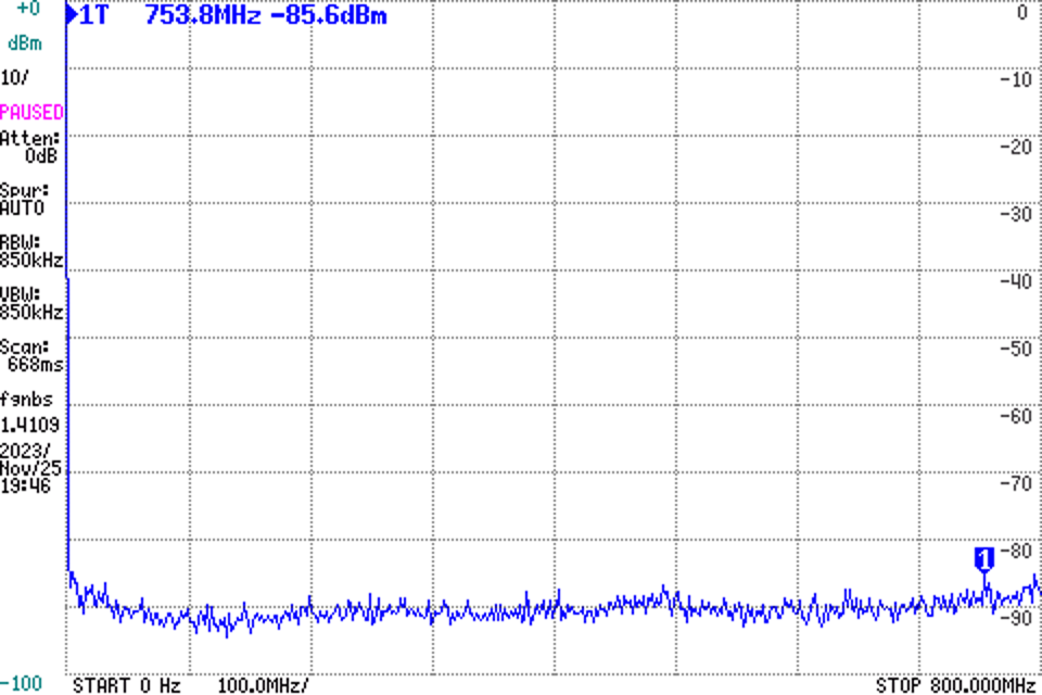
Above is a screen capture of the TinySA Ultra with current probe as pictured and plugged into a computer to capture the screen. At the time, a nearby transmitter was keyed up at 100W into the station antenna, and there is no sign of the transmitter in the trace. Fears expressed by online experts of induction via the unshielded case or the USB cable are perhaps unfounded.
The noise floor is around -90dBm which equates to -90dBA or 32µA (in 850kHz BW).
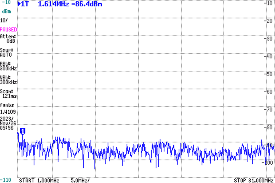
Above, a narrower scan (1-31MHz) with BW 300kHz reduces the noise floor.
Calibration
The probe is designed to produce approximately 0dBm in a 50Ω load at 1A input. So, 0dBA produces 0dBm at the 50Ω load. In the original power meter design, there is provision for a calibration constant to correct any residual error. Most Spectrum analysers have a facility to apply a small dB correction and could be used for this purpose.
Precautions
If using this with a high powered transmitter, I recommend that a equality cable is used and the SMA connectors are tightened with a torque wrench, all to ensure fully functional shielding.