RF compensation of power relays referred to a video I have recently posted RF compensation of power relays.
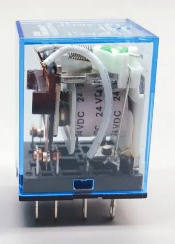
Above, the example relay.
So, does this technique work for bigger relays?
Firstly, small is beautiful… it is easier to get good compensation of smaller relays over a wider frequency range.
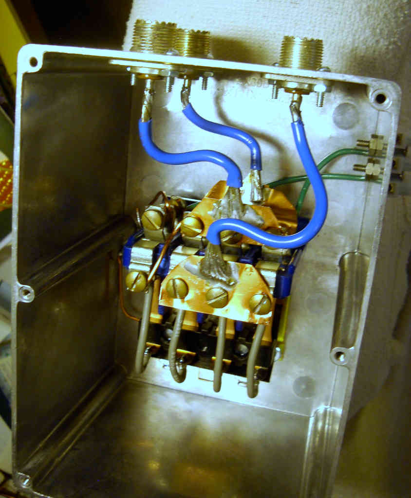
Above is an example relay by K5UJ for discussion. I do not have measurement data for this relay box, but experience tells me that at HF, the compensation technique discussed above is likely to give good results for its intended purpose as a HF T/R relay.
One should not obsess over instrument quality Insertion VSWR when UHF series connectors are used.
Using the SWAG method, I estimate that the path from input connector to output connector can probably be modelled well as an inductance of about 100nH. That model would result in an Insertion VSWR(50) of around 1.5 at 30MHz… poorer than one might want.
Let’s consider a worse case of the same topology where the path from input connector to output connector can probably be modelled well as an inductance of 200nH.
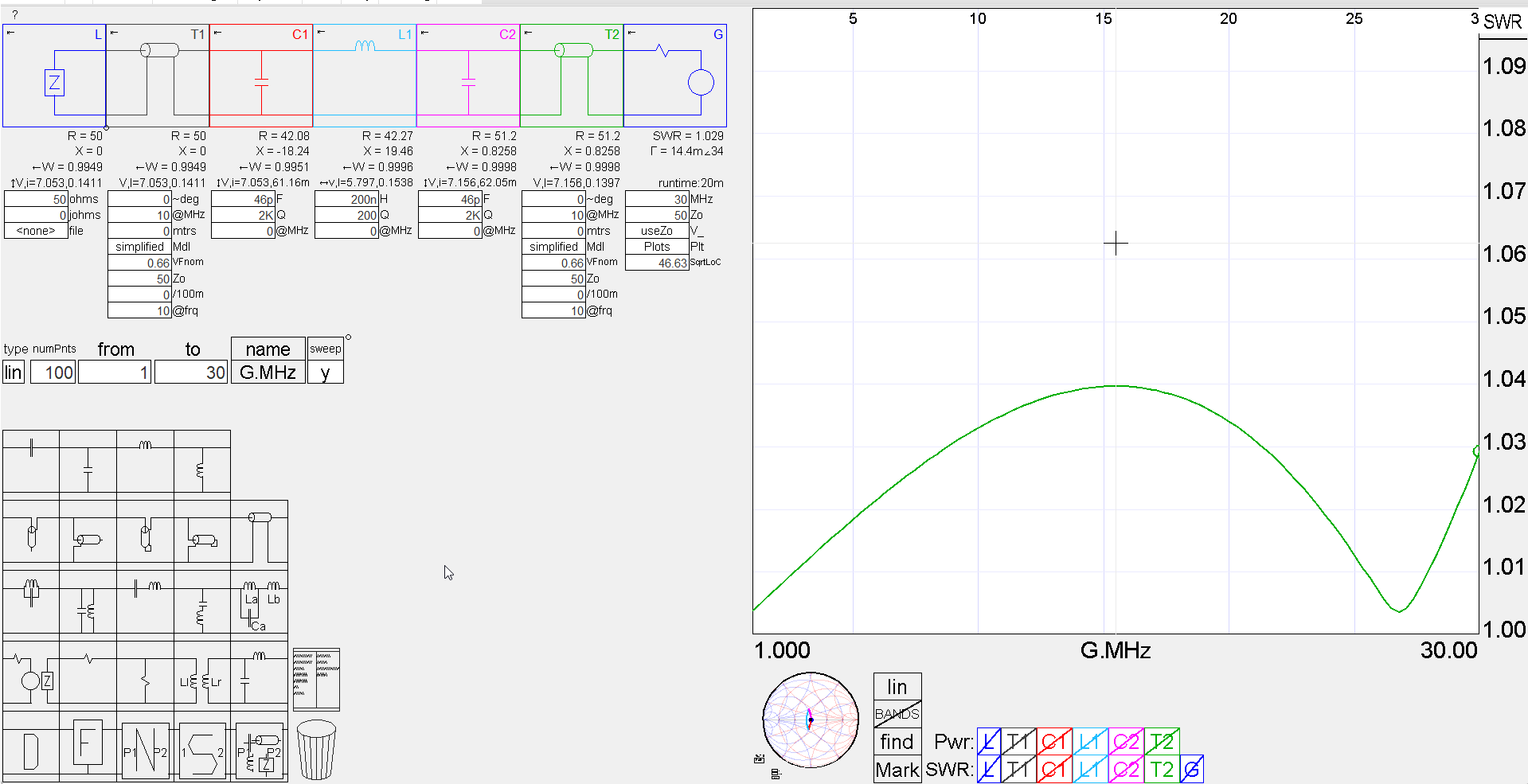
Above is a model of the compensated relay using 46pF capacitors at the coax connectors (ie three 46 capacitors, one on each connector). Obviously you are going to need parallel capacitors, perhaps 39pF and 6.8pF.
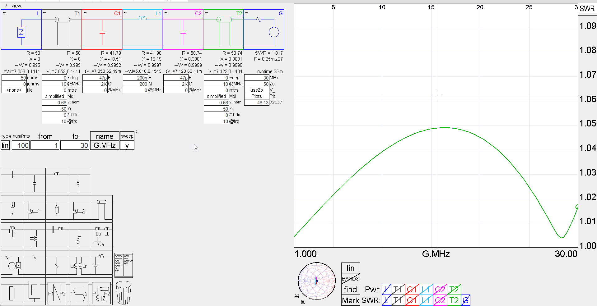
You might just accept 47pF and the slight overcompensation (above).
Now this is a fairly extreme case, with good layouts, compensation capacitance of the order of 10pF is more likely. This might be conveniently obtained with a short coax open circuit stub, such as discussed at Exploiting your antenna analyser #23. In that case, a single capacitance was used, and it was provided by about 60mm of RG58 OC stub.
Returning to the base case of 50nH equivalent for the relay path, let’s look at a Simsmith model with coax stubs for compensation.
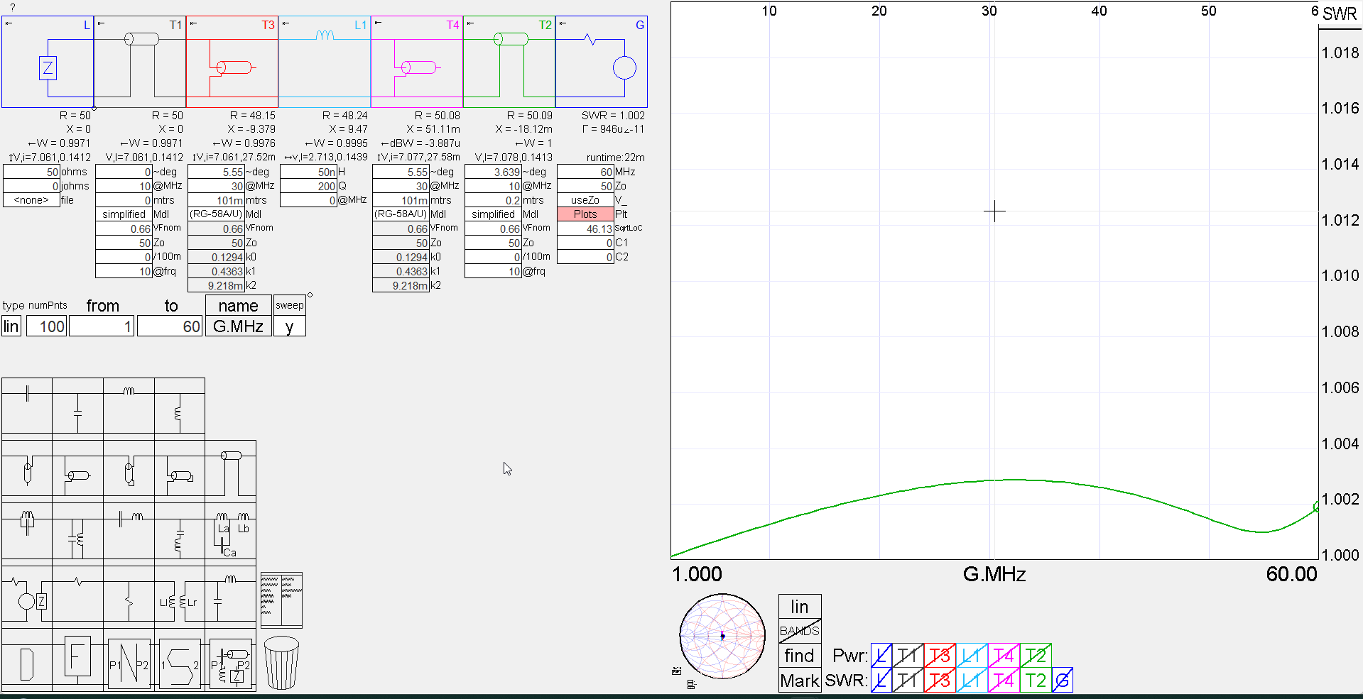
Above is the Simsmith model. So an implementation of this would be coax from the box connectors to the relay contacts, three stub coaxes connected to the contacts and all six shields twisted together and soldered really close to the ends of the coax. Keep all coax pigtails as short as possible, and protect the ends of the coax stubs (eg strip 5mm of braid from the end, and serve over with heatshrink tube.