
It seems a new version of Rigexpert Antscope has been released, and although it does increase the scale limits available for R,X plots to +/-2000Ω, it still does not allow the range permitted by v4.2.57 (+/-5000Ω).
Back to v4.2.57.
It seems a new version of Rigexpert Antscope has been released, and although it does increase the scale limits available for R,X plots to +/-2000Ω, it still does not allow the range permitted by v4.2.57 (+/-5000Ω).
Back to v4.2.57.
A common task is to measure the velocity factor of a sample of coaxial transmission line using an instrument without using SOL calibration.
Whilst this seems a trivial task with a modern antenna analyser, it seems to challenge many hams.
We will use a little test fixture that I made for measuring small components, and for which I have made test loads for SOL calibration. We will find the frequency where reactance passes through zero at the first parallel resonance of an O/C stub section, this is at a length of approximately λ/2 (a good approximation for low loss coaxial cables above about 10MHz).
We will use a little test fixture that I made for measuring small components, and for which I have made test loads for SOL calibration.
The text fixture used for this demonstration is constructed on a SMA(M) PCB connector using some machined pin connector strip and N(M)-SMA(F) adapters to connect to the instrument.
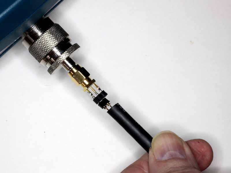
Above is a pic of the test fixture with adapters (in this case on a AA-600). Continue reading Exploiting your antenna analyser #25
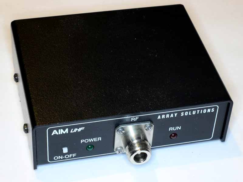
A common task is to measure the velocity factor of a sample of coaxial transmission line using an instrument that supports SOL calibration, an AIMuhf in this example.
Whilst this seems a trivial task with a modern antenna analyser, it seems to challenge many hams.
There are a thousand recipes, I am going to demonstrate just one that suits the instrument and application.
We will use a little test fixture that I made for measuring small components, and for which I have made test loads for SOL calibration. We will find the frequency where reactance passes through zero at the first parallel resonance of an O/C stub section, this is at a length of approximately λ/2 (a good approximation for low loss coaxial cables above about 10MHz).
The text fixture used for this demonstration is constructed on a SMA(M) PCB connector using some machined pin connector strip and N(M)-SMA(F) adapters to connect to the instrument.
Above is a pic of the test fixture with adapters (in this case on a AA-600). Continue reading Exploiting your antenna analyser #24
This article describes a pulse generator for adjustment of SSB RF power amplifiers.
Valve RF power amplifiers usually use high voltage power supplies with poor regulation, and typically the voltage may sag by 10% or more on full power CW output, whilst on SSB telephony the voltage may sag a quarter of that.
The effect is that finding PA loading conditions for maximum power output on a key down CW signal optimises the loading for conditions that are significantly different to SSB telephony and not only is the maximum power output likely to be lower for key down CW, but it will be lower when used for SSB telephony than if it were adjusted using a drive that created full output power without sagging the power supply more than speech would.
Additionally, RF PAs intended for the amateur market cannot sustain key down CW for very long before overheating and sustaining damage forcing very short adjustment sessions. Adjustment at continuous maximum power puts great demands on a dummy load if one is being used.
So, to solve these problems, there are three objective:
Continue reading Transmitter pulse generator for SSB RF PA adjustment
I was browsing Joe Hallas’ award winning article Antenna analysers – the basics in Aug 2016 QST when I saw some welcome news.
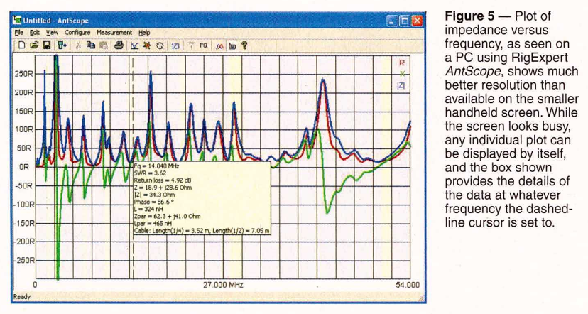
In the notes to this graphic, Joe tells us that you can display any “individual plot” in Antscope. I would dearly like to NOT display the |Z| curve which is apparently there as a concession to the ham audience that doesn’t understand the complex nature of Z and the need to see it in two dimensions. Continue reading Antenna analysers – the basics – QST Aug 2016
Seeing recent discussion by online experts insisting that power relays are not suitable to RF prompts an interesting and relevant application of a good antenna analyser.
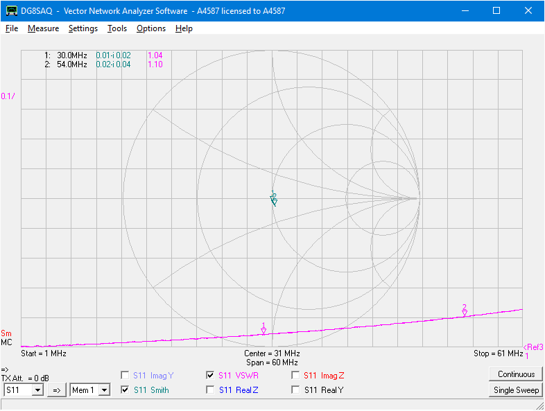
Above is a sweep of an A/B changeover relay intended for HF application at up to 100W and lowish VSWR. The sweep is actually from 1 to 61MHz to be confident that there is not poor behaviour just outside of the HF range that might present on another implementation of the same design. Continue reading Exploiting your antenna analyser #23
At Accuracy of AIMuhf system – AIM910A vs several recent versions on a ferrite cored inductor I reported significant problems reconciling several recent versions of AIM software measuring the same inductor. Continue reading Accuracy of AIMuhf system – AIM910B vs several recent versions on a ferrite cored inductor
The Red Dot 2016A is a digital HF+ VSWR meter.
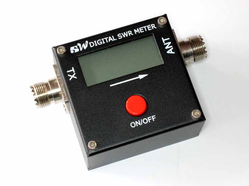
The frequency range is specified as 1.6-60MHz. Continue reading InsertionVSWR of Red Dot 2016A
The findings at InsertionVSWR of Revex W560 on HF and the suggestion that the low frequency problem is characteristic of poorly designed Sontheimer couplers (Sontheimer, C & Frederick 1966).
These couplers were popularised by (Grebenkemper 1987) in his Tandem Match – An Accurate Directional Wattmeter and have appeared in ARRL handbooks over the decades, and may have inspired the many commercial implementations of the coupler.
Grebenkemper claims his meter is ‘good’ down to 1.8MHz, but does not clearly claim any particular InsertionVSWR. There is limited value in an instrument that can measure down to 1.05 when it causes significantly higher VSWR itself.

Lets drill down on Gebenkember’s article, specifically the coupler design.
Continue reading InsertionVSWR of Grebenkemper’s Tandem Match
The Revex W560 is a dual range VSWR meter that was also sold under other brand names.

The low frequency range is specified as 1.8-160MHz. Continue reading InsertionVSWR of Revex W560 on HF