Some recent articles discussed some effects that in part are a result of Zo having a complex value (ie a non-zero imaginary part). Continue reading On working with complex Zo
Category: Transmission lines
On the concept of that P=Pfwd-Prev
The article On negative VSWR – Return Loss implications raised the question of the validity of the concept of that P=Pfwd-Prev.
The Superposition Theorem is an important tool in linear circuit analysis, and is used to find the combined response of independent sources. Superposition applies to voltages and currents, but not power. Continue reading On the concept of that P=Pfwd-Prev
On negative VSWR – Return Loss implications
On negative VSWR (read it first) discussed the case of negative VSWR results from some calculating tools and formulas, and more generally that simple formulas that depend on lossless line assumptions produce errors on practical lossy line scenarios.
Return Loss is defined as the ratio Pfwd/Prev, often given in dB.
Return Loss is usually calculated as 20*log(1/ρ), it yields negative calculated Return Loss for ρ>1. It would be a mistake to doctor the result to hide the negative return loss as it is a strong hint that the results may be invalid.
An important consideration here is the validity of the concept of Pfwd and Prev. Continue reading On negative VSWR – Return Loss implications
On negative VSWR – a worked example
On negative VSWR (read it first) discussed the case of negative VSWR results from some calculating tools and formulas, and more generally that simple formulas that depend on lossless line assumptions produce errors on practical lossy line scenarios.
This article exposes an example at 100kHz where Zo=50.71-j8.35Ω and Zload=5+j50Ω.
If we were to use a probe to directly measure the magnitude of line voltage, we would expect the following.
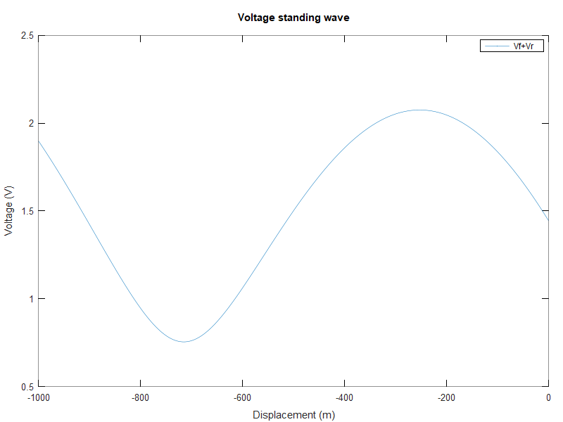
Above, the standing wave plot. At first appearance it might look like a classic standing wave plot, but it is not… there is a tiny difference in the shape at the right hand side. Continue reading On negative VSWR – a worked example
On negative VSWR
Some calculating tools come up with a negative value of VSWR under some circumstances.
Considering the meaning of VSWR: the ratio of the voltage maximum on a long transmission line to the adjacent voltage minimum, calculated negative VSWR might seem an aberration, invalid even. Note that nothing in this definition makes VSWR a property of a dimensionless point on a line.
VSWR can be measured directly by sampling voltage along a transmission line with a voltage probe. That said, it is almost never done and VSWR is inferred from other measurements, usually point measurements.
A transmission line is free to carry waves in two directions, and the ratio of voltage to current for each of those waves is the characteristic impedance Zo. Continue reading On negative VSWR
The private and public scope of coaxial cable
Let’s start by reviewing the concept of inductance.
Inductance
Inductance of a conductor is the property that a change in current in a conductor causes a electro motive force (emf or voltage) to be induced in a conductor.
We can speak of self inductance where the voltage is induced in the same conductor as the changing current, or mutual inductance where the changing current in one conductor induces a voltage in another conductor. Continue reading The private and public scope of coaxial cable
Exploiting your antenna analyser #30
Quality of termination used for calibration
Some of us use a resistor as a load for testing a transmitter or other RF source. In this application they are often rated for quite high power and commonly called a dummy load. In that role, they usually do not need to be of highly accurate impedance, and commercial dummy loads will often be specified to have maximum VSWR in the range 1.1 to 1.5 (Return Loss (RL) from 26 to 14dB) over a specified frequency range.
We also use a known value resistor for measurement purposes, and often relatively low power rating but higher impedance accuracy. They are commonly caused terminations, and will often be specified to have maximum VSWR in the range 1.01 to 1.1 (RL from 46 to 26dB) over a specified frequency range.
Return Loss
It is more logical to discuss this subject in terms of Return Loss rather than VSWR.
Return Loss is defined as the ratio of incident to reflected power at a reference plane of a network. It is expressed in dB as 20*log(Vfwd/Vref). Continue reading Exploiting your antenna analyser #30
Pawsey Balun – what is it good for?
The Pawsey Balun (or Pawsey Stub) is described as a device for connecting an unbalanced feed to a balanced antenna.

Above is a diagram of a Pawsey Balun used with a half wave dipole (ARRL).
Pawsey Balun on an asymmetric load reported model results in an asymetric dipole antenna, and showed very high common mode feed line current.
Pawsey Balun on an asymmetric load – bench load simulation showed that although the Pawsey balun is not of itself an effective voltage balun or current balun, it can be augmented to be one or the other.
So, you might ask what they do, what they are good for, and why they are used. Continue reading Pawsey Balun – what is it good for?
Pawsey Balun on an asymmetric load – bench load simulation
The Pawsey Balun (or Pawsey Stub) is described as a device for connecting an unbalanced feed to a balanced antenna.
Pawsey Balun on an asymmetric load reported model results in an asymetric dipole antenna, and showed very high common mode feed line current.
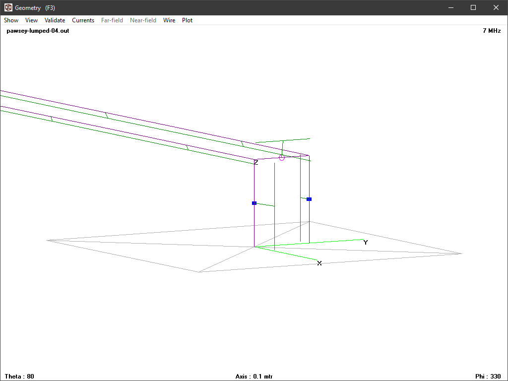
This article looks at two test bench configurations modelled in NEC.
The configurations are of a horizontal Pawsey balun for 7MHz constructed 0.1m over a perfect ground plane. The ‘balanced’ terminals are attached to the ground plan by two short 0.1m vertical conductors which are loaded with 33 and 66Ω resistances. At the other end, the horizontal transmission line is extended by two different lengths and connected to the ground plane using a 0.1m vertical conductor. The two extension lengths are almost zero and a quarter wavelength.
Zero extension
The total horizontal length from the ‘balanced terminals’ to the grounded end of the transmission line is a quarter wavelength for the Pawsey balun and a further 20mm making approximately a quarter wavelength in total.
Above is a plot of current magnitude and phase from 4NEC2. The current on the two vertical conductors containing the 33 and 66Ω loads is quite different, and the product gives load voltages that are approximately equal in magnitude and opposite in phase. Continue reading Pawsey Balun on an asymmetric load – bench load simulation
Pawsey Balun on an asymmetric load
The Pawsey Balun (or Pawsey Stub) is described as a device for connecting an unbalanced feed to a balanced antenna.
Above is a diagram of a Pawsey Balun used with a half wave dipole (ARRL).
Whilst these have been quite popular with VHF/UHF antennas, the question arises as to how they work, and whether they are effective in reducing common mode current IIcm) for a wide range of load scenarios. Continue reading Pawsey Balun on an asymmetric load