Small efficient matching transformer for an EFHW – a Simsmith model

This article offers a simple Simsmith model for the Small efficient matching transformer for an EFHW.

Above is the model topology. D1 is a daemon block which essentially, calculates key values for the other blocks based on exposed parameters and the named ferrite material complex permeability data file. The prototype used a Fair-rite 2643625002 (#43) core. Continue reading Small efficient matching transformer for an EFHW – a Simsmith model

A simple generic Simsmith model of a linear push-pull Class B broadband HF power amplifier

This article outlines a Simsmith model developed to explore / confirm behavior of some linear Class B push-pull HF broadband power amplifiers.

The design is for a system power output of about 80W on a 24V supply, it is a combination that should work with practical system components with good efficiency.

Above is a first step, an estimate of an initial load line for the PA. The calculator is written in valve terms, but is quite applicable to this scenario. Continue reading A simple generic Simsmith model of a linear push-pull Class B broadband HF power amplifier

Ferrite cored inductors at HF – flux, loss and saturation

I see online experts opine that small signal characteristics (eg complex permeability curves) of ferrite toroids are not valid for applications such as RF common mode choke in transmitting antennas.

Others opine that saturation is a practical design limit, and for example that Bs/2 is a safe / appropriate design target.

Let us consider a ferrite cored inductor at 7MHz. The inductor comprises 11t on a 11t on Fair-rite 5943003801 (FT240-43) toroid. This is a medium to high permeability ferrite material, and for that reason, has significant loss at HF. Higher and lower permeability materials are fashionable at different times, the higher permeability #31 mix is fashionable at this time.

I will work in MKS units.

Above is Fair-rite’s B-H curves for #43 material. Let’s take saturation flux density Bs to be 1500gauss or 0.15T. Continue reading Ferrite cored inductors at HF – flux, loss and saturation

EB104 alternative output circuit

One of the very important designs of HF broadband MOSFET power amplifiers was that of Helge Granberg in Motorola application note EB104.

This article offers an explanation of how the the alternative output circuit at Fig 5 of EB104 works.

Let’s look at the schematic diagram of the PA.

Above is the schematic from EB104, of interest for this article is the output circuit comprising T2 and T3 which are intended ideally to provide a drain to drain load of 50/9=5.55Ω. Continue reading EB104 alternative output circuit

A desk review of the MiniPa100 kit – #2: transformer T2 turns ratio

This article is on in a series of a desk review, a pre-purchase study if you like, of the MiniPa100 kit widely sold on eBay and elsewhere online.

Previously

The above pic from an eBay advertisement of the 2020 version of the PA would suggest very strongly that there are three turns on the secondary of the output transformer, and a half turn on each drain. Interestingly the 70W versions also appear to use three turns, alarm bells ring!

Here is a little table that shows the maximum power obtainable with a transformer of this type for various supply voltages and secondary turns. Continue reading A desk review of the MiniPa100 kit – #2: transformer T2 turns ratio

Desk study of M0DGQ’s 150W HF PA

M0DGQ described a broadband HF PA in the Wythal Radio Club’s newsletter 2017-01, and rated it at 150W output. Note that this module does not include the necessary output filter which will probably lose 5-10% of the power from this module.

The PA uses a MRF9180 dual MOSFET operating on 26V supply.

Above is the prototype PA. The text states very clearly that the output transformer uses a secondary of two turns of PTFE insulated wire, and the pic above does not provide evidence to the contrary.

Hmmm, experience suggests that may be too few turns. Continue reading Desk study of M0DGQ’s 150W HF PA

A desk review of the MiniPa100 kit – #1: characterise the output transformer

This article is one in a series of a desk review, a pre-purchase study if you like, of the MiniPa100 kit widely sold on eBay and elsewhere online.

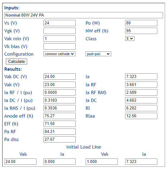
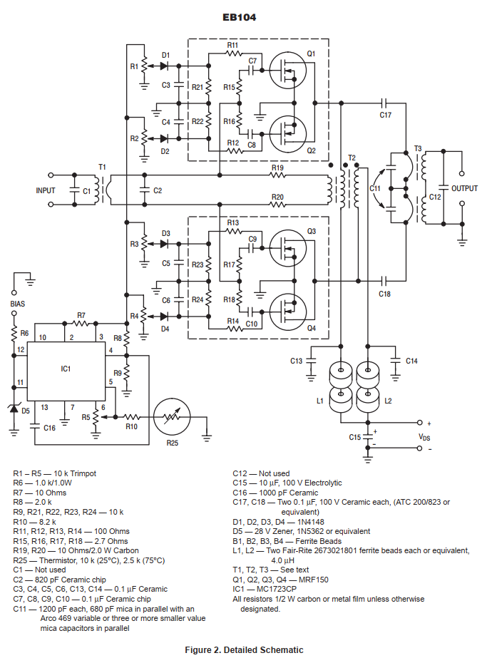
One of the first questions to mind is whether it is likely to deliver the rated power, so let’s review the MOSFET output circuit design from that perspective.

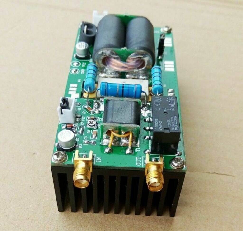
Sellers mostly seem to need to obscure the MOSFET type in their pics, so essentially you buy this with no assurance as to what is supplied, no comeback if the supplied MOSFET is not up to the task. Online experts suggest the MOSFET is probably a MRF9120 (or 2x IRF640 in a 70W build). The amplifier claims 100W from 12-16V DC supply.

Note that this module does not include the necessary output filter which will lose 5-10% of the power from this module.

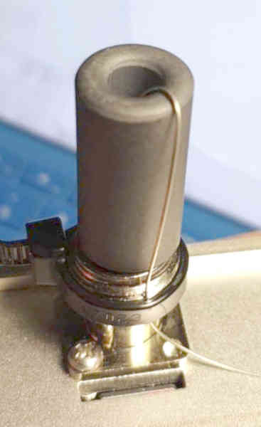
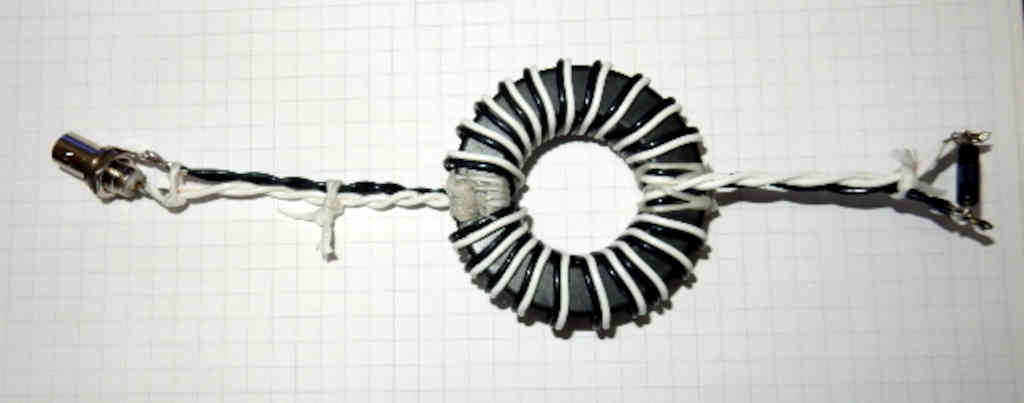
In this case Carlos, VK1EA, connected a sample output transformer (T2) core from a recently purchased MiniPa100 kit to a EU1KY antenna analyser. The fixture is critically important, it is at my specification. Continue reading A desk review of the MiniPa100 kit – #1: characterise the output transformer

(How) does this balun work? A variation on the theme …

My article (How) does this balun work analysed a balun configuration sent to me by a correspondent, apparently published on Youtube channel TrxBench.

Essentially, my analysis was that it comprises two 12t winds of two wire transmission line in parallel on the ferrite ring. The potential benefit was that the characteristic impedance Zo of each transmission line is probably close to 100Ω, and the parallel combination is probably close to 50Ω.

Online experts following fashion are opining that a low Insertion VSWR balun is better made with two wire line(s) than winding a single 50Ω coax line. They make these claims without evidence, I am not convinced.

In that vein, here is a variation on the TrxBench balun above.

The designer describes it: Continue reading (How) does this balun work? A variation on the theme …

Some pretty woolly thinking on measuring Thevenin equivalent source impedance of a ham transmitter

A ham seeking to optimise his station based on some measurements with a VNA and some modelling of a matching network posted the results of a test in the process.

The radio is an Icom IC-7300. I bypassed the built in tuner, transmitted a tone into my external tuner, adjusted it for SWR=1. I then disconnected the tuner from the radio, and measured the impedance looking into the tuner with a VNA. Surprisingly, (to me anyway) the result was a pretty good 53-j3 Ohms at 14 MHz.

What should we / have expected? It is an interesting case to study. Continue reading Some pretty woolly thinking on measuring Thevenin equivalent source impedance of a ham transmitter

Collins 30-L1 on FT-8

After a lot of grief with Excel trying to open and fix some 10 year old spreadsheets… finally…

I was recently asked about FT-8 on the Colling 30-L1 linear amplifier considering my article Collins 30L-1 and AM.

The first thing to note is the Colling 30-L1 manual cautions against AM and FSK:

That said, what are the reasons for such a prohibition? Continue reading Collins 30-L1 on FT-8