Effect of shorting turns on a tapped air cored solenoid at RF offers a simple model for estimating the effect of shorting turns on inductance (L) and Q.
A correspondent sent me a set of measurements he made of an air cored solenoid using a Q meter.
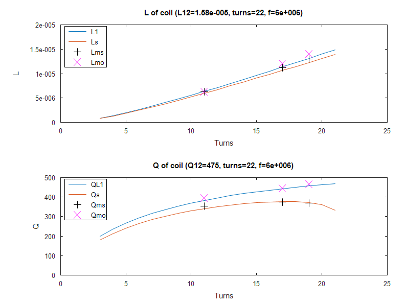
The coil was a 22t air solenoid of length 99.5mm and radius 31.56mm. Q of the whole coil (L12) was measured at 6MHz to be 475.
L and Q were estimated and measured with three different tapping points at one end of the coil.
Whilst the method described in the reference article does not attempt to estimate the effect of tapping where the unused turns are left open circuit, we might expect than when the unused section is a small part of the coil, that the effect is similar to that if the unused turns were not there.
A model as described in the reference article was constructed.
The notation is L1 is the used part of the coil, L2 is the unused part, L12 is the whole coil with no taps, Lms is measured L unused shorted, Lmo is measured L unused open, like wise for the Q subscripts.

Above, the model results There is quite good reconciliation with the predicted behaviour. Continue reading Effect of shorting turns on a tapped air cored solenoid at RF #2
Last update: 29th March, 2018, 11:53 AM
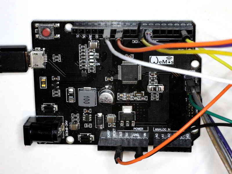
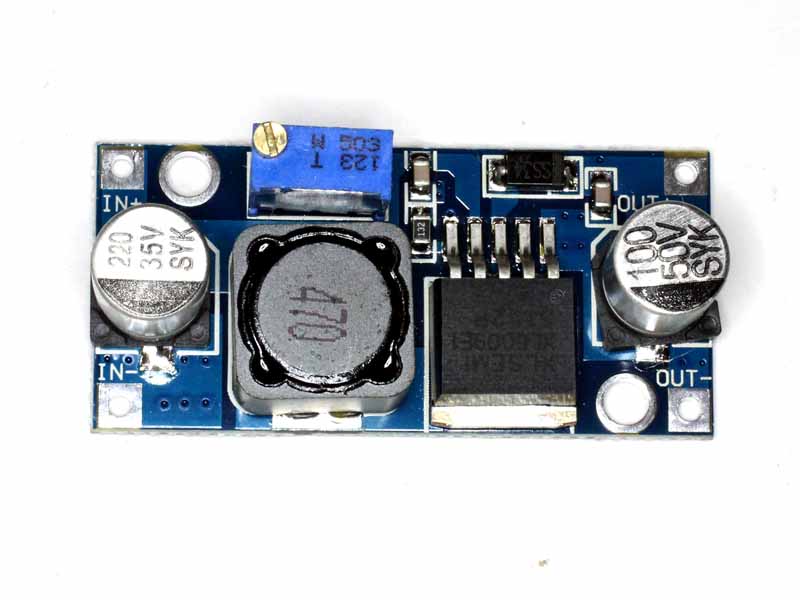
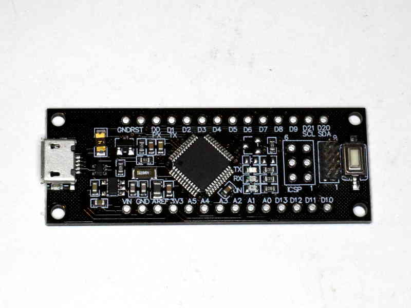 Above is one of the culprit boards. Continue reading Arduino SAMD21 bootloader protection