I rode my motorcycle over to visit Ray, VK2COX, and we rode our bikes across to Canowindra (pronounced /kəˈnaʊndrə/ kə-NOWN-drə) for a burger at the famous Garden of Roses Cafe.
Over lunch, Ray described his new cigarette packet sized CW rig build that he would take up onto the local hill on his block for a little play, and told me he was going to jam his favorite 3xNE555 CW keyer into it.
I offered to design him an accurate keyer based on an 8 legged DIP chip and less than a dozen parts overall. I designed the logic in my head on the way home to Canberra, and started programming it that night in May 2001.
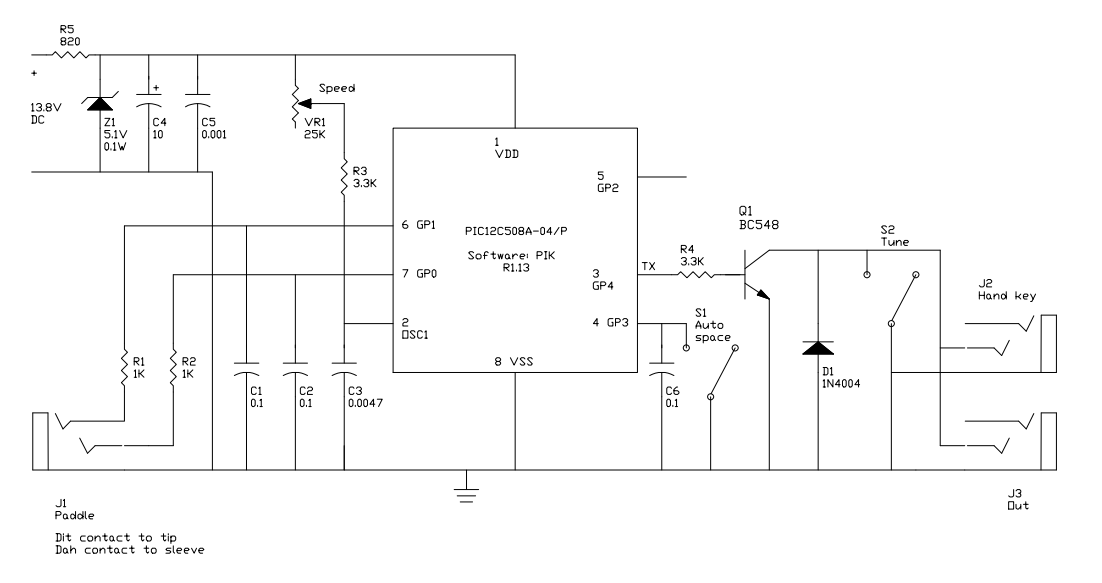
The PIK is described at PIK – PIC Iambic Keyer. Above is the generic circuit diagram of the PIK.
Ray wanted to dispense with the pot for setting speed, and a variant with an on-off-on switch was designed to allow three speeds to his specification.
This one runs on 4.5V from 3 x AA cells. A 3000mAh battery will run it in ‘sleep’ mode for around 2,000,000 hours or 230 years… the shelf life of the batteries determines their useful life and there is consequently no ON/OFF switch. It did fit inside the small transmitter case, and he reported that it worked very well, so well he built another (with the speed pot) for bench use in his home station.
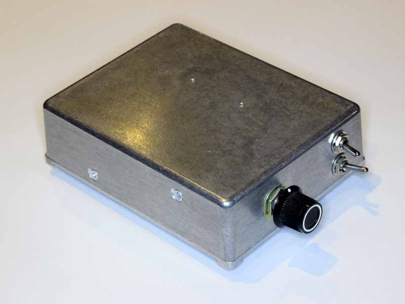
Above is the external view of my own PIK keyer prior to labelling.
Lots of these were built by people, the firmware was available for download so I do not know of all the instances that were built. I distributed more than a hundred chips personally.
I do know that they became popular with the Morsecodians Fraternity who were mostly long retired line telegraphists who enjoyed passing traffic between each other using dial up modems to make a connection and simulate the telegraph line. As age took hold, some found they could no longer manipulate the hand key, but could paddle their way along using the PIK.