Voltage symmetry of practical Ruthroff 4:1 baluns – finding TLT Vout/Vin

I have been asked to expand on the calculation of voltage magnitude and phase set out in Voltage symmetry of practical Ruthroff 4:1 baluns.

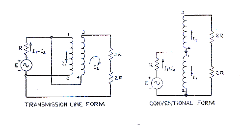
Above is Ruthroff’s equivalent circuit, Fig 3 from his paper (Ruthroff 1959). Focusing on the left hand circuit which explains the balun as a transmission line transformer (TLT), and taking the node 1 as the reference, the loaded source voltage appears at the bottom end of the combined 4R load, and transformed by the transmission line  formed by the two wires of the winding, and inverted, at the top end of the combined 4R load.

It is the transformation on this transmission line that gives rise to loss of symmetry.

The complex ratio Vout/Vin is dependent on the complex reflection coefficient Gamma at both ends of the line and the line propagation constant gamma, all of which are frequency dependent complex quantities. Continue reading Voltage symmetry of practical Ruthroff 4:1 baluns – finding TLT Vout/Vin

A low Insertion VSWR high Zcm Guanella 1:1 balun for HF – more detail #3

This article expands on the detail behind A low Insertion VSWR high Zcm Guanella 1:1 balun for HF with focus on InsertionVSWR and possible compensation schemes.

A low Insertion VSWR high Zcm Guanella 1:1 balun for HF – more detail #2 discussed the imperfection caused by the quite short pigtails, and although small, it is measurable.

Chris, NX0E, related experience with Dr E M T Jones at TCI where they made, among other things, TCI’s HF baluns. These baluns were compensated using capacitors, and we see that very occasionally in ham grade baluns.

The pigtails can be seen as a short transmission line of higher Zo, and although not uniform, it provides a model for understanding their effect.

Above is a Simsmith model that treats the pigtails as short sections of 300Ω line, the lengths adjusted to calibrate the model to the observed impedance at 30MHz.
Continue reading A low Insertion VSWR high Zcm Guanella 1:1 balun for HF – more detail #3

A low Insertion VSWR high Zcm Guanella 1:1 balun for HF – more detail #2

This article expands on the detail behind A low Insertion VSWR high Zcm Guanella 1:1 balun for HF with focus on InsertionVSWR.

Insertion VSWR is the VSWR looking into the balun with a matched load (termination) on its output, it is a measure of imperfection of the balun. It ought to be a specification item for low Insertion VSWR baluns, but it rarely given.

What is not mentioned in the above definition is the symmetry or balance of the load.

Above is a Smith chart plot of input Z of the balun with an isolated load of 50+j0Ω. Isolated to mean that there is no direct path from either load terminal to ground, it could be seen as a symmetric load with extremely high common mode impedance. All of the external connections use N type connectors with Zo=50Ω.
Continue reading A low Insertion VSWR high Zcm Guanella 1:1 balun for HF – more detail #2

De-embedding transmission line to allow remote measurement

Recent articles An interesting case study of measurement of a balun’s Insertion VSWR and Another measurement of a balun’s Insertion VSWR made measurements through a transmission line of the load on a balun.

In the first article, the measurements at the input of around 7m of 50Ω line were adjusted to move the reference plane to the load end of the coax using the add/subtract cable feature of Antscope to de-embed the transmission line.

The second article used a FA-VA5 analyser and VNWA software to make the measurements and to some extent, de-embed the transmission line. In this case the transmission line was quite short at 370mm, and whilst the facility adjusted for propagation time, it did not adjust for attenuation though that was very small in this case and of little consequence. The FA-VA5 analyser and VNWA software combination would not suit the scenario in the first article as will be demonstrated.

This article examines the response to a 6m length of RG58 with O/C load at 30MHz.

We can see that although the phase of Gamma (phase of 0.85+j0.01) is close to zero the magnitude is 0.85 when the magnitude should be 1.00 for an O/C load. Continue reading De-embedding transmission line to allow remote measurement

Another measurement of a balun’s Insertion VSWR

Further to An interesting case study of measurement of a balun’s Insertion VSWR, this article presents similar measurements of a small DIY balun.

Balun404

Above is the top view of the balun, and the test termination comprised two 100Ω 1% resistors clamped between the screw terminals, so pigtails were just 3mm in length.

Balun402

Above is a view of the interior.The coax pigtails are quite short, they exist at the input and output. Continue reading Another measurement of a balun’s Insertion VSWR

An interesting case study of measurement of a balun’s Insertion VSWR

Jeff, 2E0CIT, sent me a Rigexpert AA-170 measurement file of his test of Insertion VSWR of a commercial balun.

Insertion VSWR is the VSWR looking into the balun with a matched load (termination) on its output, it is a measure of imperfection of the balun. It ought to be a specification item for low Insertion VSWR baluns, but it rarely given.

A broadband low Insertion VSWR balun must be wound with a transmission line of the nominal impedance, 50Ω in this case, and in the case of 50Ω , it is most likely to be coax.

Above is the initial VSWR plot received. The VSWR response is poorer than one might want in a low Insertion VSWR balun… but to drill down on the reasons, the Smith chart view of the data gives insight. Continue reading An interesting case study of measurement of a balun’s Insertion VSWR

Choosing a toroidal magnetic core – ID and OD

One sees lots of articles describing inductors and transformers wound on rectangular cross section ferrite cores, and in explanations, the OD seems to be an important parameter but little consideration is given to ID.

Inductance of an inductor on a rectangular toroidal core depends on many factors, and among them ID and OD. Inductance is proportional to ln(OD/ID).

Above is a plot of the factor ln(OD/ID) against ID/OD as a percentage. It can be seen that for ID/OD approaching unity (ie a radially ‘thin’ toroidal core) that the characteristic is almost linear, and inductance is proportional to the radial thickness of the core. Continue reading Choosing a toroidal magnetic core – ID and OD

W0SJ matching transformer for an EFLW (Laird 28B1540-000)

QST publishes a design by W0SJ for a nominal 50:450Ω EFLW matching device from 160-10m using the following circuit.

The article is ‘in-brief’ as technical stuff that will not interest most hams is published privately on a members-only page. This article is based on the information in the QST article alone (ie not on the private members only supplementary information).

The core has a modest price in North America, but shipping to other parts of the world may make it very expensive… IOW unobtainium to most parts of the world.

Above is the published InsertionLoss. The article states that they were half the value obtained in a back to back measurement, and it should be noted that is a compromised measurement, and secondly that InsertionLoss comprises two components, (dissipative) Loss and MismatchLoss. Continue reading W0SJ matching transformer for an EFLW (Laird 28B1540-000)

Online expert on coax loss

An online expert opined:

Whether your antenna is a perfect 1:1 or a 10:1, a 50 foot length of coax will have HALF the loss of the exact same coax on the exact same antenna system as measured with the 100 foot piece.

Is it true? Can we learn from it?

Let’s take a worked example of Belden 8259 (RG58A/U) with a load of 5+j0Ω at 146MHz. VSWR is approximately 10. Continue reading Online expert on coax loss

Voltage symmetry of practical Ruthroff 1:1 baluns

Well, I guess Voltage symmetry of practical Ruthroff 4:1 baluns begs the question, what about Ruthroff 1:1 voltage baluns?

The Ruthroff 1:1 voltage balun can be seen as two back to back Ruthroff 4:1 voltage baluns with the redundant winding removed… and that prompts the thinking that the cascade of two baluns back to front might cancel the phase delay.

Let’s measure a popular Ruthroff 1:1 voltage balun.

RAK BL-50A

Above, the RAK BL-50A was a quite popular balun, and probably the balun of choice for half wave dipoles… well until the message about current baluns escaped. Continue reading Voltage symmetry of practical Ruthroff 1:1 baluns