Comparison of BN43-202 / 5t with BN73-202 / 2t for rx only on low HF – small broadband RF transformer – 50:200Ω

Several correspondents refer to my article Feasibility study – loop in ground for rx only on low HF – small broadband RF transformer using medium µ ferrite core for receiving use – 50:200Ω and suggest “I got it wrong, #73 is the proven material choice for such a thing, and a 2t primary is optimal”.

In fact, I did explore #73 as an option, this article presents some key comparisons. The two key statistics shown in this article provided the basis for selecting the design.

Note that the scales are different from plot to plot.

Insertion VSWR

Where the magnetising impedance appears in shunt with an ideal transformer with Zin=50+j0Ω, Insertion VSWR can be calculated.

2t on BN73-202

5t on BN43-202

Continue reading Comparison of BN43-202 / 5t with BN73-202 / 2t for rx only on low HF – small broadband RF transformer – 50:200Ω

RF transformer design with ferrite cores – saturation calcs

Ferrite cored inductors and transformers saturate at relatively low magnetising force.

#61 material example

Lets work through an example of a FT50-61 core with 10t primary at 3.5MHz.

Magnetic saturation is one limit on power handling capacity of such a transformer, and likely the most significant one for very low loss cores (#61 material losses are very low at 3.5MHz).

Let’s calculate the expected magnetising impedance @ 3.5MHz.

Zm=0.966+j144Ω, |Zm|=144Ω. Continue reading RF transformer design with ferrite cores – saturation calcs

RF transformer design with ferrite cores – initial steps

A review of transformer design

In a process of designing a transformer, we often start with an approximate low frequency equivalent circuit. “Low frequency” is a relative term, it means at frequencies where each winding current phase is uniform, and the effects of distributed capacitance are insignificant.

Above is a commonly used low frequency equivalent of a transformer. Z1 and Z2 represent leakage impedances (ie the effect of magnetic flux leakage) and winding conductor loss. Zm is the magnetising impedance and represents the self inductance of the primary winding and core losses (hysteresis and eddy current losses). Continue reading RF transformer design with ferrite cores – initial steps

An online expert on the unsuitability of #43 for HF UNUNs

An online expert recently advised:

…The spec for type 43 makes it clear that it should never be used for HF unun construction. It is specifically engineered with a complex permeability that makes the core lossy on most HF frequencies. Since an unun is not a TLT (transmission line transformer) but rather an autotransformer, a low loss core is essential for efficient operation….

Now it contains the very common FUD (fear, uncertainty and doubt) that masquerades as science in ham radio, but without being specific enough to prove it categorically wrong. To a certain extent, the discussion goes to the meaning of efficient operation. Continue reading An online expert on the unsuitability of #43 for HF UNUNs

Exploiting your antenna analyser #30

Quality of termination used for calibration

Some of us use a resistor as a load for testing a transmitter or other RF source. In this application they are often rated for quite high power and commonly called a dummy load. In that role, they usually do not need to be of highly accurate impedance, and commercial dummy loads will often be specified to have maximum VSWR in the range 1.1 to 1.5 (Return Loss (RL) from 26 to 14dB) over a specified frequency range.

We also use a known value resistor for measurement purposes, and often relatively low power rating but higher impedance accuracy. They are commonly caused terminations, and will often be specified to have maximum VSWR in the range 1.01 to 1.1 (RL from 46 to 26dB) over a specified frequency range.

Return Loss

It is more logical to discuss this subject in terms of Return Loss rather than VSWR.

Return Loss is defined as the ratio of incident to reflected power at a reference plane of a network. It is expressed in dB as 20*log(Vfwd/Vref). Continue reading Exploiting your antenna analyser #30

EFHW exploration – Part 2: practical examples of EFHW

EFHW exploration – Part 1: basic EFHW explored the basic half wave dipole driven by an integral source as a means of understanding that component of a bigger antenna system.

The EFHW can be deployed in a miriad of topologies, this article goes on to explore three popular practical means of feeding such a dipole.

The models are of the antenna system over average ground, and do not include conductive support structures (eg towers / masts), other conductors (power lines, antennas, conductors on or in buildings). Note that the model results apply to the exact scenarios, and extrapolation to other scenarios may introduce significant error.

End Fed Zepp with current drive

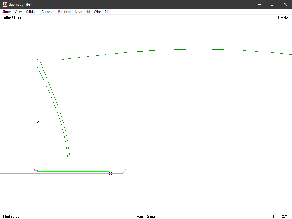
A very old end fed antenna system is the End Fed Zepp. In this example, a half wave dipole at λ/4 height is driven with a λ/4 600Ω vertical feed line driven by a balanced current source (ie an effective current balun).

Above is a plot of the current magnitudes. The currents on the feed line conductor are almost exactly antiphase, and the plot of magnitude shows that they are equal at the bottom but not so at the top. The difference between the currents is the total common mode current, and it is maximum at the top and tapers down to zero at the bottom. Icm at the top is about one third of the current at the middle of the dipole. Continue reading EFHW exploration – Part 2: practical examples of EFHW

EFHW exploration – Part 1: basic EFHW

The so-called End Fed Half Wave (EFHW) has become very fashionable amongst hams. The idea of end feeding a half wave antenna is hardly new, and there is widespread use of the broad concept… but from online ham discussion, it can be observed that the things are not well understood and indeed, there is magic about them.

A simple model of a simple antenna

This article presents some NEC-4.2 model results for a 7MHz λ/2 horizontal 2mm copper wire at height of λ/4 above average ground.

The model is impractical in a sense that it does not include unavoidable by-products of a practical way to supply RF power to the antenna, but it is useful in providing insight into the basic antenna.

The NEC model has 200 segments, and varying the feed segment gives insight to what happens to feed point impedance.

Above, it can be seen that as the wire is fed closer to the end (segment 1), feed point Z includes a rapidly increase capacitive reactance. Continue reading EFHW exploration – Part 1: basic EFHW

W0SJ matching transformer for an EFLW (Laird 28B1540-000)

QST publishes a design by W0SJ for a nominal 50:450Ω EFLW matching device from 160-10m using the following circuit.

The article is ‘in-brief’ as technical stuff that will not interest most hams is published privately on a members-only page. This article is based on the information in the QST article alone (ie not on the private members only supplementary information).

The core has a modest price in North America, but shipping to other parts of the world may make it very expensive… IOW unobtainium to most parts of the world.

Above is the published InsertionLoss. The article states that they were half the value obtained in a back to back measurement, and it should be noted that is a compromised measurement, and secondly that InsertionLoss comprises two components, (dissipative) Loss and MismatchLoss. Continue reading W0SJ matching transformer for an EFLW (Laird 28B1540-000)

AIM 916 produces internally inconsistent results


AIMuhf

AIM915a was recently pulled from the distribution site and replaced by a new release, AIM916.

AIM916 chokes on some calibration files created with earlier versions, so again historical scan data is rendered worthless. Note the illogical diagnostic message… typical AIM quality.

I cannot recall ever finding a new release that did not have significant defects, commonly inconsistency between displayed values. In the common theme of one step forward, two steps backwards, this version has defects that were not present in AIM910B.

This problem existed in AIM915a, it persists in AIM916.

Let’s review the internal consistency of this part of the display screen.

Most of the values given above are calculated from a single measurement value, and should be internally consistent. That measurement value is translated to different quantities, many based on the stated Zref (50Ω in this case). Continue reading AIM 916 produces internally inconsistent results

Elecraft CP-1 directional coupler – magnetics review

Elecraft produces a directional coupler that may interest QRP aficionados. It comes with instructions for 20dB and 30dB coupling factors rated at 25 and 250W respectively from 1 to 30MHz.

This article reviews the magnetics design of the -20dB / 25W coupler.

The coupler uses a type of Sontheimer coupler (Sontheimer 1966) and these are commonly poorly designed. The first question is whether the magnetising impedance of T2 which appears in shunt with the load is sufficiently high to not give rise to poor insertion VSWR. Continue reading Elecraft CP-1 directional coupler – magnetics review