Basic measurements of the VK3AMP Sontheimer directional coupler for a N2PK wattmeter

This article documents measurement and analysis of a VK3AMP Sontheimer directional coupler in an implementation of a 400W wattmeter design by N2PK (Kiciack nd).

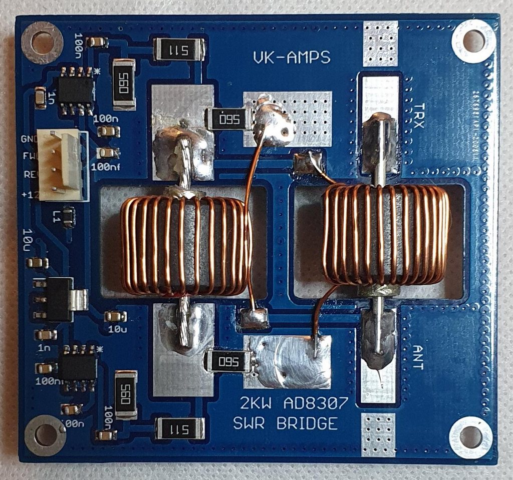
I purchased one of the couplers for use with a DIY digital display, and although I have had it longer, it isn’t yet realised!

A common failing of almost all hammy Sammy designs is appalling InsertionVSWR at the lower end of the specified frequency range. This coupler is specified for 1.8-54MHz, and differently to most, has meaningful published characteristics.

In this implementation, 60mm lengths of solder soaked braid coax similar to Succoform 141 were used between the PCB and box N connectors. The expected matched line loss of both of these is about 0.01dB @ 50MHz.

The measurements here were made by VK4MQ using an Agilent E5061A ENA, data analysis by myself.

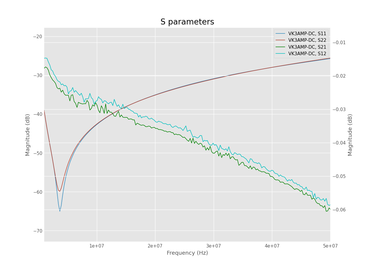
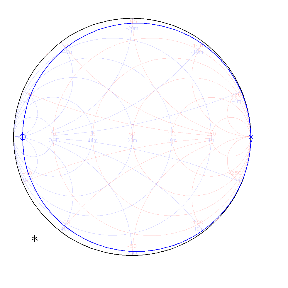
Above are the raw s parameter measurements plotted. It is a full 2 port measurement, and it can be observed that the device is not perfectly symmetric, quite adequate, and quite good compared to other ham designs that I have measured. Continue reading Basic measurements of the VK3AMP Sontheimer directional coupler for a N2PK wattmeter

Failure estimating transmission line Zo – λ/8 method – nanoVNA – Smith chart perspective

Failure estimating transmission line Zo – λ/8 method – nanoVNA discussed traps in using the λ/8 method to estimate Zo… it is not the no-brainer that is often suggested.

This article shows the use of the Smith chart to look for departures from pure transmission line behavior in that test, or any other that depends on measuring purely Zin of a length of line in purely differential mode with short circuit or open circuit termination.

Above is a Smith chart plot of what we should see looking into a line of similar characteristic swept from 1 to 20MHz. There is no magic there, this is basic transmission lines and Smith chart. Continue reading Failure estimating transmission line Zo – λ/8 method – nanoVNA – Smith chart perspective

Failure estimating transmission line Zo – λ/8 method – nanoVNA

Countless online discussions have online experts describing their various preferred methods for estimating the characteristic impedance of a transmission line… often without really testing whether their simple results are realistic, ie believable. Of course, being social media, it would be unsocial for another participant to question the results, so the unchallenged becomes part of ham lore.

Apparent gross failures are often wrongly attributed to factors like manufacturing tolerances, polluted line surface, other esoteric factors etc that might imply a knowledgeable author… but that is social media, an unreliable source of information.

Let’s explore an estimate using measurements with a nanoVNA using the popular eighth wavelength (λ/8) method.

λ/8 method

The λ/8 method relies upon the property of a lossless line terminated in an open circuit that differential impedance \(Z_d=\jmath X=- \jmath \left| Z_0 \right| cot \left(\pi/4\right)=- \jmath\left| Z_0 \right|\). So, if you measure the reactance looking into the λ/8 (\(\frac{\piᶜ}{4} \:or\: 45°\)), you can estimate Zo as equal to the magnitude of the reactance.

A similar expression can be written for the case of a short circuit termination and it leads to the same result that you can estimate Zo as equal to the magnitude of the reactance (an exercise for the reader).

The fact that the two cases lead to the same result can be used to verify that the line length is in fact λ/8 (they will not be equal if the length is a little different to λ/8)… though writeups rarely mention this, or perform the test.

So, the method depends critically on:

  • whether the line length is λ/8;
  • whether it is sufficiently low loss; and
  • whether the differential impedance measurement is valid.

Most online articles do not include details of the measurement setup, perhaps thinking that it not all that relevant. Of course, one of the greatest failings in experiments is to ignore some factor that is in fact relevant. Continue reading Failure estimating transmission line Zo – λ/8 method – nanoVNA

Select a ferrite core material and sufficient primary turns for a low InsertionVSWR 50Ω broadband RF transformer – comparison of measured and predicted

Select a ferrite core material and sufficient primary turns for a low InsertionVSWR 50Ω broadband RF transformer – nanoVNA described a method of using a nanoVNA to select by trial possible core and turns combinations for a transformer.

This article compares the results for the FT240-43 example at 3.5MHz with calculation using tools on this web site.

Simple low frequency equivalent circuit

Above is a very simple approximation of an ideal 1:1 transformer where the effects of flux leakage and conductor loss are ignored. A 1:n transformer can be modelled the same way, as if flux leakage and conductor loss are ignored, the now ideally transformed secondary load becomes 50Ω. Continue reading Select a ferrite core material and sufficient primary turns for a low InsertionVSWR 50Ω broadband RF transformer – comparison of measured and predicted

Fair-rite’s ‘new’ #43 permeability data (2020)

Fair-rite publishes spreadsheets of the complex permeability characteristic of many of the ferrite mixes. This note is about #43 mix and clarification I sought from Fair-rite.

Question

I note that recently, the published table of #43 permeability changed subtly but significantly. Does this table apply to historical product, or does it only apply to new product, ie was there an actual change in the mix, or what it the result of better measurement of characteristics?

Continue reading Fair-rite’s ‘new’ #43 permeability data (2020)

Surely there cannot be more forward power than the transmitter makes?

Let’s explore a simple numerical example of a practical line operating in Transverse Electro Magnetic (TEM) mode (the usual thing for practical coax lines at HF).

Let’s review the meaning of 50Ω line.

It means that the line geometry imposes a natural constraint on a wave travelling in the line that V/I=50… but remember that TEM waves are free to travel in (only) two directions. This natural ratio of V/I is called the characteristic impedance Zo. Continue reading Surely there cannot be more forward power than the transmitter makes?

Select a ferrite core material and sufficient primary turns for a low InsertionVSWR 50Ω broadband RF transformer – nanoVNA – loss components graph

Select a ferrite core material and sufficient primary turns for a low InsertionVSWR 50Ω broadband RF transformer – nanoVNA gave an explanation of how to use a nanoVNA or the like to select a suitable core and sufficient turns for a low InsertionVSWR broad band 50Ω transformer. Continue reading Select a ferrite core material and sufficient primary turns for a low InsertionVSWR 50Ω broadband RF transformer – nanoVNA – loss components graph

A DIY thermostat based on the MS1230A controller

This article documents the build of a DIY thermostat based on an inexpensive ($12) Chinese temperature controller.

Controller module

The controller used is a 220VAC MH1230A.

Above is an internal view of the controller. Importantly it has a relay rated at 240V 30A, and 15A at PF=0.4. The datasheet rates the relay for a 2HP (1.5kW) motor. It uses a ‘conventional’ power supply, the brown component is the power transformer. Most similar products use inadequate relays and have low grade switched mode power supplies that create RF noise. Continue reading A DIY thermostat based on the MS1230A controller

Select a ferrite core material and sufficient primary turns for a low InsertionVSWR 50Ω broadband RF transformer – nanoVNA

This article demonstrates the use of a nanoVNA to select a ferrite core material and sufficient primary turns for a low InsertionVSWR 50Ω broadband RF transformer.

Simple low frequency equivalent circuit

Above is a very simple approximation of an ideal 1:1 transformer where the effects of flux leakage and conductor loss are ignored. A 1:n transformer can be modelled the same way, as if flux leakage and conductor loss are ignored, the now ideally transformed secondary load becomes 50Ω. Continue reading Select a ferrite core material and sufficient primary turns for a low InsertionVSWR 50Ω broadband RF transformer – nanoVNA