A recent video explained how to use a Smith chart to solve a series single stub match using coax.
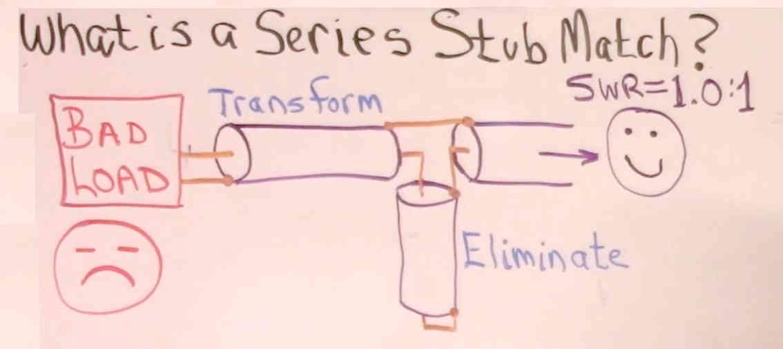
The diagram above from the video shows the topology of the series stub match. Continue reading Pitfalls of series stub matching with coax
A recent video explained how to use a Smith chart to solve a series single stub match using coax.
The diagram above from the video shows the topology of the series stub match. Continue reading Pitfalls of series stub matching with coax
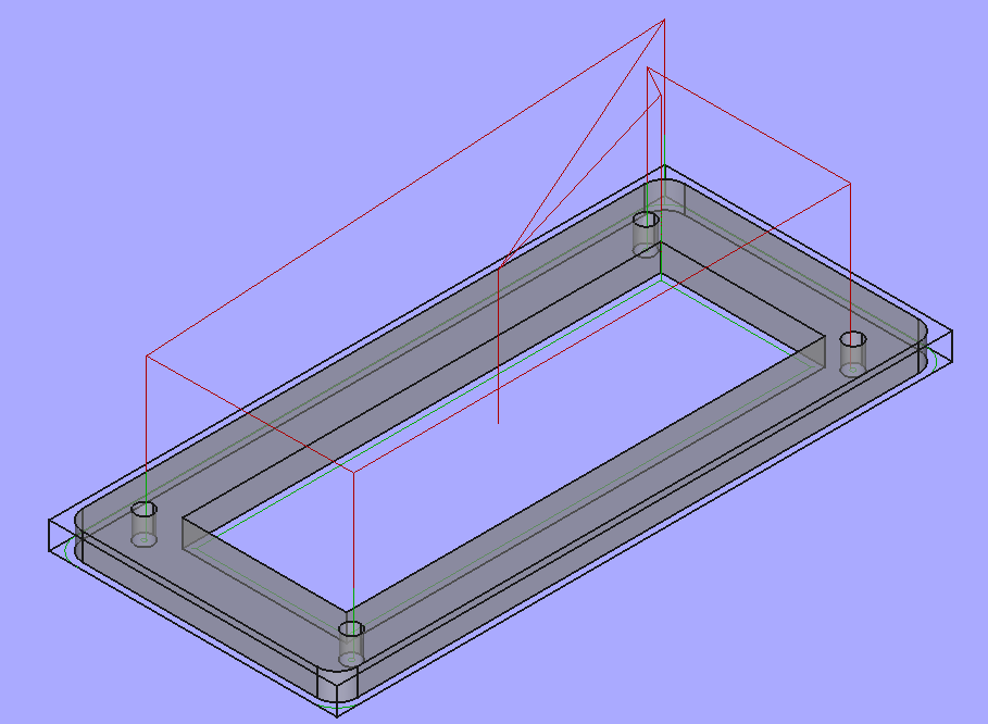
This article describes a coil former made from 3mm cast acrylic, cut on a CNC router, part designed in Freecad. The project is really an exploration of manufacture of one on my CNC router.
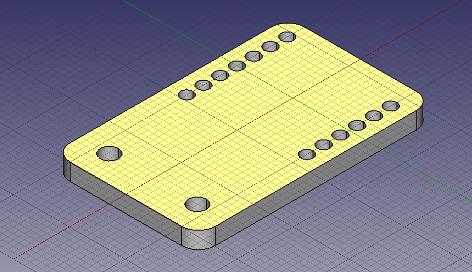
Above is a 3D view of the part design. Continue reading Coil former made of cast acrylic sheet
A chap posted a pic and some mini VNA measurement results of a resistor which he reported has a DC resistance of 80Ω.

Above is part of the pic, focusing on the ‘fixture’. The chap reports that the VNA was OSL calibrated, and we might assume that was at the SMA(M) connector (it is difficult to explain the results if the reference plane was at the VNA jack). Continue reading An interesting study in the effect of fixture on impedance measurement
A reader of A common scheme for narrow band match of an end fed high Z antenna commented:
…if the coil is tapped at 1/3, surely then the coil is a 1:3^2 or 1:9 transformer and the capacitor simply ‘tunes out’ the coil reactance, what is the input impedance when it has a 450+j0Ω load?
That is very easy to calculate in the existing Simsmith model.

Above, with load of 450+j0Ω, the input impedance at 50MHz is 8.78+j34.36Ω (VSWR50=8.4), nothing like 50+j0Ω. Continue reading A common scheme for narrow band match of an end fed high Z antenna – surely it is a 1:9 transformer?
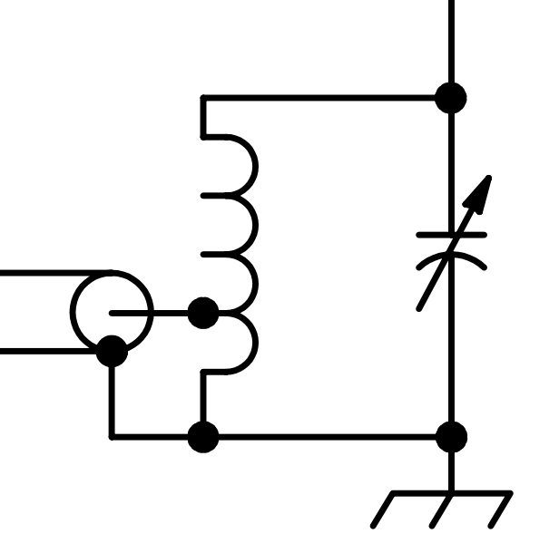
This article discusses the kind of matching network in the following figure.
A common variant shows no capacitor… but for most loads, the capacitance is essential to its operation, even if it is incidental to the inductor or as often the case, supplied by the mounting arrangement of a vertical radiator tube to the mast. Continue reading A common scheme for narrow band match of an end fed high Z antenna
One of the magic ham recipes often proposed is to stack two ferrite cores of different permeability for an RF inductor, but an explanation is rarely offered, I have not seen one.
Starting with some basic magnetism…
The inductance of an inductor is given by \(L=N\frac{\phi}{I}\).
For a closed magnetic circuit of high permeability such as a ferrite cored toroid, the flux is almost entirely contained in the core and the relationship is \(\mathcal{F}=\phi \mathcal{R}\) where \(\mathcal{F}\) is the magnetomotive force, \(\phi\) is the flux, and \(\mathcal{R}\) is the magnetic reluctance. (Note the similarity to Ohm’s law.) Continue reading Stacking two ferrite cores of different permeability for an RF inductor
A correspondent asked about the difference between two small untune loops mentioned in two of my articles, this article explains.
Firstly lets set the context, a small loop means less than λ/10 perimeter, and untuned is to mean that the loop is loaded directly, in this case by a receiver which we will assume has an input impedance of 50+j0Ω.
Let’s look at the two cases. The key difference is in the connection at the gap:
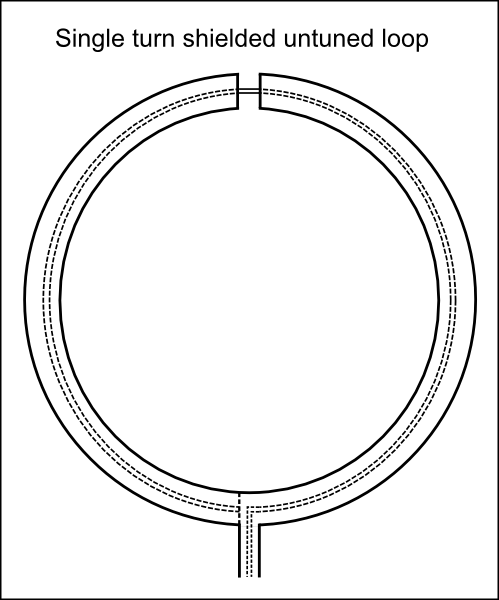
Above is a diagram of the loop. Continue reading Differences in two similar simple untuned small loop configurations
This article describes a small matching transformer built and measured by Luis, CT2FZI, using a Fair-rite 2643251002.
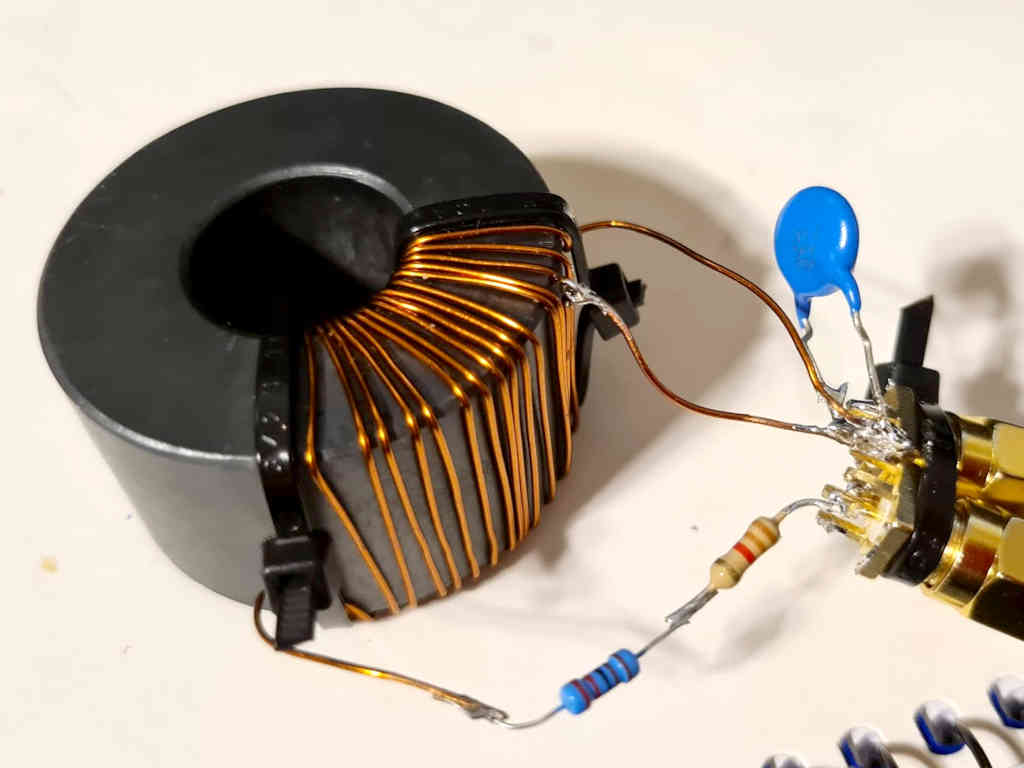
Above is the transformer with 100pF compensation capacitor across the input, and two resistors to make up a 3300Ω load in combination with the VNA port. Continue reading Another small efficient matching transformer for an EFHW – 2643251002
A chap recently posted some advice on construction of a dual ratio transformer for EFFHW antennas, advice with an informative pic, but without measurement evidence that it works well.
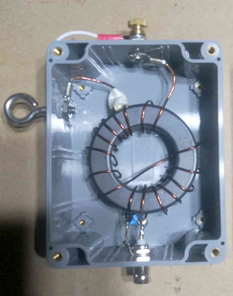
Pictured is a dual UnUn. I made this for experimenting. It’s both a 49 and 64 to 1 UnUn.
The 49 to 1 tap uses the SS eye bolt for the feed through electrical connection and the SS machine screw on the top is the 64 to 1 connection. If I want to use the 49 to 1 ratio, there’s a jumper on the eye bolt that connects to the top machine screw where the antenna wire is attached. The jumper shorts out the last two turns of the UnUn. Disconnect the jumper from the top connection and now you have a 64 to 1 ratio.
Continue reading Shorting winding sections of a ferrite cored EFHW transformer
RF Power Meter 2 is a logging RF power meter based on AD8307 and ESP8266.
The original LCD display was white on blue, but was very difficult to read at some viewing angles, so it had to go. Unfortunately I could not find more displays with that hole pattern, it seems to have been discarded for a newer hole pattern as almost everything I looked at had the same newer patter.
So, the box front needed rework, and there would be visible spare holes… so a dress escutcheon was designed in Freecad and cut on a CNC router.
The escutcheon was designed to be cut from some 3mm black acrylic sheet that was on hand, and it would cover the reworked panel. Continue reading RF Power Meter 2 (RFPM2) – display update