Rigexpert AA-600 N connector dimensions

A recent post by David Knight described dimensional issues with the N connector on his AA-600 and problems with the seller in having it resolved.

Warned of a potential quality issue, I measured my own AA-600.

Above, the test of the inner pin forward surface distance from the reference plane on the N jack on the AA-600. The acceptable range on this gauge for the female connector is the red area, and it is comfortably within the red range.

Above is a table of critical dimensions for ‘ordinary’ (ie not precision) N type connectors from Amphenol.

This dimension is important, as if the centre pin protrudes too much, it may damage the mating connector.

Pleased to say mine is ok, FP at 0.192″.

I used a purpose made gauge to check this, but it can be done with care with a digital caliper (or dial caliper or vernier caliper), that is what I did for decades before acquiring the dial gauge above.

nanoVNA-H – measure ferrite transformer – Noelec balun

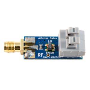
At nanoVNA-H – measure ferrite transformer I gave an example of using a nanovna to measure loss of a ferrite cored transformer.

Noelec makes a small transformer, the Balun One Nine, pictured above and they offer a set of |s11| and |s12| curves in a back to back test. (Note: back to back tests are not a very reliable test.) Continue reading nanoVNA-H – measure ferrite transformer – Noelec balun

VSWR ripple

Having seen some recent discussion where the online experts opined that an example given of a VSWR plot that contained a fairly consistent ripple was quite normal, this article suggests there is an obvious possible explanation and that to treat it as quite normal may be to ignore the information presented.

Above is a partial simulation of a scenario using Rigexpert’s Antscope. It starts with an actual measurement of a Diamond X-50N around 146MHz with the actual feed line de-embedded. Then a 100m lossless feed line of VF=0.66 is simulated to produce the plot that contains a ripple apparently superimposed on an expected V shaped VSWR curve.

This is the type of ripple that the expert’s opine is quite normal. Continue reading VSWR ripple

nanoVNA-H – woolly thinking on MLL measurement

There is little doubt that the nanoVNA has made VNAs very popular in the ham community, possibly more so that any other device.

Eager owners are trying to apply them to solve lots of problems, often without sufficient knowledge or experience to properly inform the measurements.

An example that has a appeared a few times on online forums in the last weeks is measuring the matched line loss (MLL) of a section of RG6 coax… to inform a decision to discard it or keep it.

The common approach is to use a measurement of |s11| and to calculate Return Loss and infer the MLL.

DUT

For discussion, lets consider an example of 30′ of Belden 1694A RG6 solved in Simsmith. We should note that unlike most RG6 in the market today, this uses a solid copper centre conductor.

Short circuit termination

Some authors insist that the half return loss method is to be performed using a short circuit test section. Bird does this in their Bird 43 manual.

Above is a plot of calculated |s11| (-ReturnLoss) from 1 to 20MHz for the test section. The three plots are of |s11| wrt 50Ω, 75Ω and frequency dependent actual Zo (as calculated for the model). The cursor shows that the actual |s11| is -0.37474dB (ReturnLoss=0.37474dB). Using the half return loss method MLL=ReturnLoss/2=0.37474=0.187dB/m. Continue reading nanoVNA-H – woolly thinking on MLL measurement

RG6 cladding thickness report

N0TZU recently report his perception that a length of Logico COX3520 RG6 Quad cable he purchased exhibited higher than expected Matched Line Loss (MLL) at 10MHz.

Most RG6 type cable sold these days at low cost uses a copper clad steel centre conductor, and much of it has insufficient copper cladding thickness for copper like performance at HF.

Above is a pic N0TZU gave of the centre conductor cross section. It is possible to measure the cladding thickness from the pic knowing that the overall diameter is 1.024mm. The copper thickness measured 13.7µm, lets round it to 14µm. Continue reading RG6 cladding thickness report

MFJ ATU hand effects on capacitor knobs

The problem

Users of some ATUs may have noticed particular sensitivity to hands on the capacitor adjustment knobs. It is a common problem with cheap implementations of the T match as the capacitor rotor is usually at high RF voltage and if that shaft is extended to the adjustment knob, under certain circumstances tuning becomes very sensitive to hands on the knobs.

In some of these implementations, if the users hand touches the metal grub screw in the knob, or the metal panel bushing behind the knob they may get a significant RF burn.

The cause

Let’s use the MFJ-949E as a discussion example. It is a T match, and the metal capacitor shafts in the knobs and panel bushings carry RF voltages.

So why is this only sometimes a problem?

The RF voltage across the coil, and impressed on the capacitor shafts can be extremely high when using loads with small resistance and large negative reactance, more so on the lower bands. Continue reading MFJ ATU hand effects on capacitor knobs

WIA 4:1 current balun – further measurements

4-101a

I mentioned in my article WIA 4:1 current balun that the use of a single toroidal core in the above graphic compromises the balun. This article presents some simple measurements and analysis that question whether the balun works as so many users think.

The popularity of the balun derives from the work of VK2DQ and is often known as the VK2DQ 4:1 current balun (though probably not his invention).

Analysis at the limits

Often, analysis of a network as frequency approaches zero or infinity can simplify the analysis whilst allowing a reasonable test of the sanity of the design.

Above is a conventional transformer schematic of the WIA 4:1 current balun on a perfectly symmetric (balanced) load. At frequencies where the electrical length of each winding is very short, we can assume negligible phase delay along or between windings, simplifying analysis greatly. Continue reading WIA 4:1 current balun – further measurements

A common mode choke for a VDSL pair – LF1260 core

This article describes a common mode choke intended to reduce RF interference with a VDSL service.

The MDF is located where the underground cable enters the building. From here it rises vertically and travels some 25m across the ceiling to the VDSL modem. Continue reading A common mode choke for a VDSL pair – LF1260 core

nanoVNA-H – measuring an inductor – is it a no-brainer?

Let’s explore measurement of a test inductor with the nanovna.

Above is the test inductor, enamelled wire on an acrylic tube.

An online expert’s advice make this task look like a no-brainer:

For a 100 nH inductor you are probably using an air wound coil so you won’t see that much change in inductance with frequency. However, inductors made with toroids will because the permeability of the core goes down with frequency.

So, this is an air cored inductor, permeability is approximately that of free space, a constant 4πe-7 independent of frequency. Nevertheless we will see that apparent inductance can change with frequency. Continue reading nanoVNA-H – measuring an inductor – is it a no-brainer?