Do I ‘need’ a masthead preamp to work satellites on 2m? – space noise scenario

A question asked online recently provides an interesting and common case to explore.

Base scenario is a low end satellite ground station:

  • 144MHz;
  • satellite;
  • IC-9700, assume NF=4.8dB;
  • high gain (narrow beamwidth antenna);
  • 10m of LMR-400.

Continue reading Do I ‘need’ a masthead preamp to work satellites on 2m? – space noise scenario

MFJ-261 – review of review

A recent review of the MFJ-261 (Bogard 2021) was interesting.


From MFJ’s web site listing:

Connects directly to the transmitter with PL-259 connector. No patch cable used, reduces SWR. Finned aluminum, air-cooled heatsink. Handles 100 Watts peak, 15 Watts average. 50 Ohms. Covers DC to 500 MHz with less than 1.15:1 SWR. 1 ⅝” round by 3″ long.

That is pretty stunning for a device with a UHF connector, more on that later. Continue reading MFJ-261 – review of review

On testing coax cable loss with an analyser / VNA – part 4

On testing coax cable loss with an analyser / VNA – part 3 drilled down on a better method of approximating the matched line loss (MLL) of a section of transmission line based on measurements of ReturnLoss with the section terminated in both an open circuit and short circuit. This article goes a little further using the saved measurement files to answer a reader’s questions.

Measurement vs TLLC & TLDetails

TLLC and TLDetails are two line loss calculators, and they use quite different predictive models.

Above is the calculation results from TLLC. for the 10m section of Belden 8267 (RG213) with short circuit termination. Note the calculated loss model coefficients k1 and k2 which will be used in a later graph. Continue reading On testing coax cable loss with an analyser / VNA – part 4

On testing coax cable loss with an analyser / VNA – part 3

On testing coax cable loss with an analyser / VNA – part 2 gave a method of approximating the matched line loss (MLL) of a section of transmission line based on measurements of ReturnLoss with the section terminated in both an open circuit and short circuit. The article demonstrated the method using TLLC to provide expected measurement values.

So, does it work in practice?

Let’s measure a 10m length of Belden 8267 (RG-213) fitted with N connectors using a Rigexpert AA-600 and an instrument grade N(F) short circuit.

ReturnLoss @ 3.5MHz is 0.15dB. Continue reading On testing coax cable loss with an analyser / VNA – part 3

On testing coax cable loss with an analyser / VNA – part 2

On testing coax cable loss with an analyser / VNA – part 1 questioned a common method of measuring Matched Line Loss (MLL) of a section of an open circuit transmission line section, posing the questions:

The example gives MLL’ (based on half ReturnLoss) of about two thirds cable MLL.

  • Why is that?

  • What does it say for the measurement technique?

Continue reading On testing coax cable loss with an analyser / VNA – part 2

On testing coax cable loss with an analyser / VNA – part 1

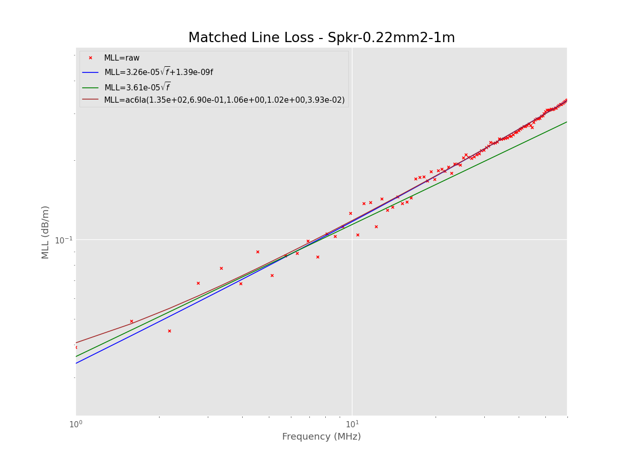
A recent online video provides instruction on how to measure loss of a section of coax cable, loss to mean Matched Line Loss, \(MLL=\frac{P_{in}}{P_{out}}\) when the cable is terminated in its characteristic impedance Zo, and which can be expressed in db as \(MLL=10 log_{10} \frac{P_{in}}{P_{out}}\). Note that MLL in dB is ALWAYS a +ve value for a passive DUT such as this.

There is nothing new in the method, it appears in lots of analyser user manuals, and has a built in assist in many analysers.

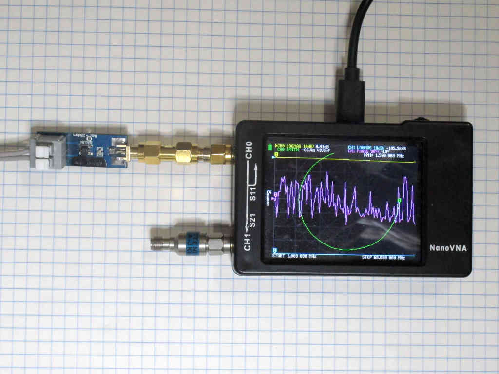
The video deals with the case of an antenna analyser that has a ‘measure cable loss’ function and using a VNA. Lets use the VNA graphic as it shows more detail of what is happening.

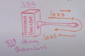
Above is the video’s graphic for the case. The narration says to use the dB magnitude of s11 or ReturnLoss as equivalents. They aren’t equivalent (a hammy Sammy thing), \(ReturnLoss=-20 log_{10}|s11|\) or \(ReturnLoss_{dB}=-s11mag_{dB}\) (both wrt the VNA reference impedance). Continue reading On testing coax cable loss with an analyser / VNA – part 1

Measuring a 1/4 wave balanced line – nanoVNA

A question was asked recently online:

I am about to measure a 1/4 wave of 450 ohm windowed twinlead for the 2m band using my NanoVNA. My question is, since I will be making an unbalanced to balanced connection, should I use a common mode choke, balun or add ferrites to the coax side to make the connection, or does it really matter at 2m frequencies? The coax lead from my VNA to the twinlead will be about 6″ to 12″ long. I will probably terminate the coax in two short wires to connect to the twinlead.

It is a common enough question and includes some related issues that are worthy of discussion. Continue reading Measuring a 1/4 wave balanced line – nanoVNA

Measure transmission line Zo – nanoVNA – PVC speaker twin – loss models comparison #3

Measure transmission line Zo – nanoVNA – PVC speaker twin demonstrated measurement of transmission line parameters of a sample of line based on measurement of the input impedances of a section of line with both a short circuit and open circuit termination. From Zsc and Zoc we can calculate the Zo, and the complex propagation constant \(\gamma=\alpha + \jmath \beta\), and from that, MLL.

Above is a plot of: Continue reading Measure transmission line Zo – nanoVNA – PVC speaker twin – loss models comparison #3

Measure transmission line Zo – nanoVNA – PVC speaker twin – loss model derivation

The article Measure transmission line Zo – nanoVNA – PVC speaker twin demonstrated measurement of transmission line parameters of a sample of line based on measurement of the input impedances of a section of line with both a short circuit and open circuit termination. From Zsc and Zoc we can calculate the Zo, and the complex propagation constant \(\gamma=\alpha + \jmath \beta\), and from that, MLL.

Measurement with nanoVNA

So, let’s measure a sample of 14×0.14, 0.22mm^2, 0.5mm dia PVC insulated small speaker twin.

Above is the nanoVNA setup for measurement. Note that common mode current on the transmission line is likely to impact the measured Zin significantly at some frequencies, the transformer balun (A 1:1 RF transformer for measurements – based on noelec 1:9 balun assembly) is to minimise the risk of that. Nevertheless, it is wise to critically review the measured |s11| for signs of ‘antenna effect’ due to common mode current. Continue reading Measure transmission line Zo – nanoVNA – PVC speaker twin – loss model derivation