Capacity test of aftermarket NB-6L batteries

I purchased two replacement batteries type NB-6L for a Canon camera.

Above, the batteries are labelled 1050mAh. They appear to be well made externally, and fit charger and camera fine.

Note that these have different labeling to that shown in the eBay listing. It is naive to expect that the supplied item matches either pics or description, bait and switch is a standard Chinese technique. Continue reading Capacity test of aftermarket NB-6L batteries

Geometry factors for some common Fair-rite binocular ferrite cores

Designing with some common Fair-rite binocular ferrite cores can be frustrating because different parameters are published for different material types, and some are controlled for different parameters.

An approach is to derive the key geometry parameter from the published impedance curves and published material complex permeability curves.

For example, the above curves for a 2843002402 (also common known as a BN43-2402) were digitised and iteratively Calculate ferrite cored inductor (from Al) used for find the value of Al that gives the observed value for Z at 10MHz on the chart above. Continue reading Geometry factors for some common Fair-rite binocular ferrite cores

Measuring trap resonant frequency with an antenna analyser – measurement of a real trap

Finding the resonant frequency of a resonant circuit such as an antenna trap is usually done by coupling a source and power sensor very loosely to the circuit.


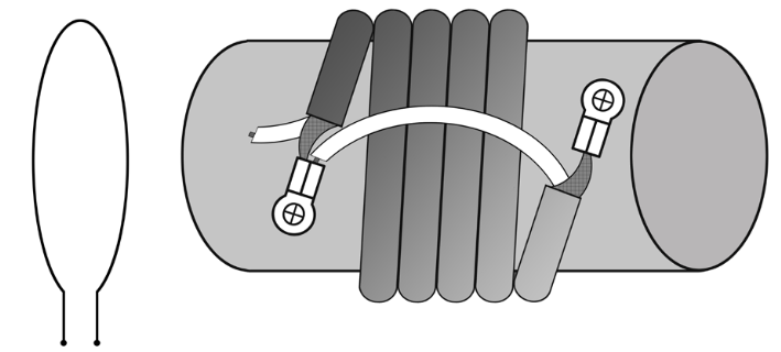
Above is Fig 1, a diagram from the Rigexpert AA35Zoom manual showing at the left a link (to be connected the analyser) and the trap (here made with coaxial cable).

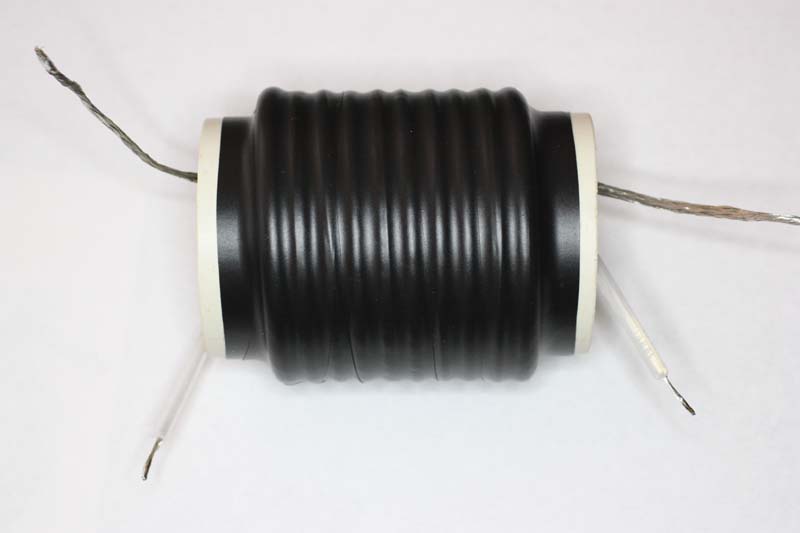
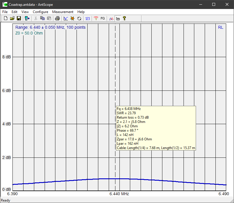
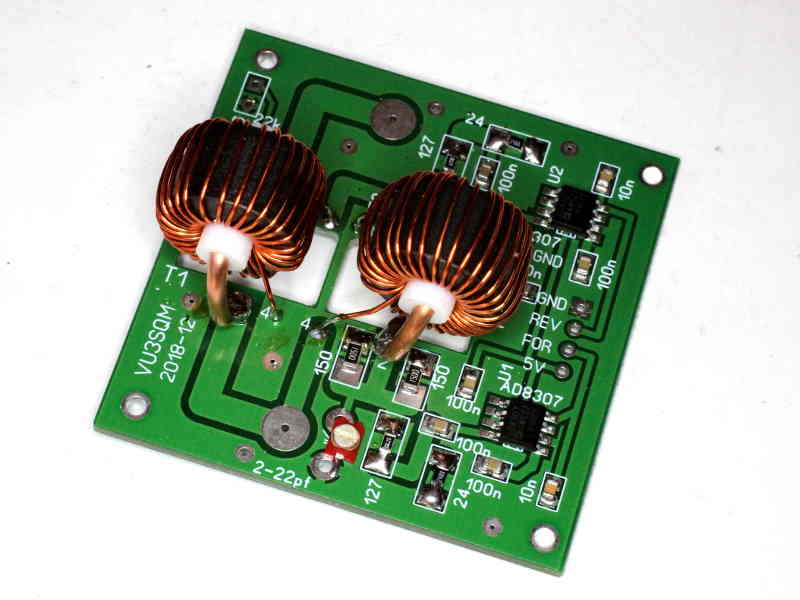
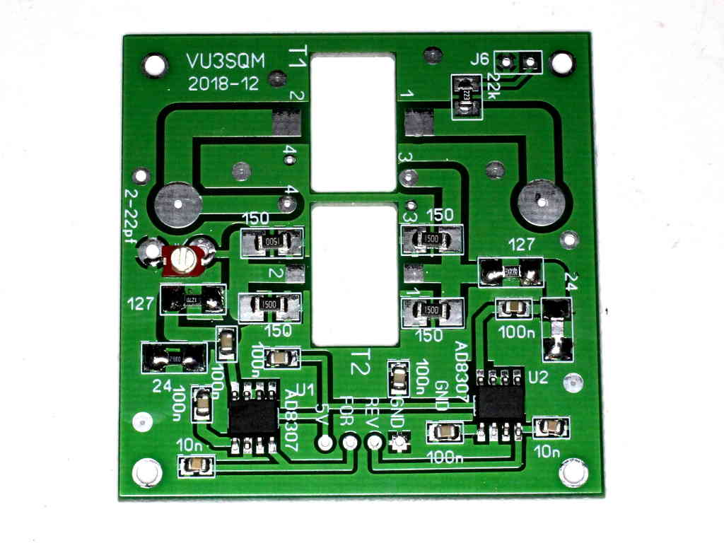
Above is the trap measured, the wires were connected as a bootstrap trap as in Fig 1. The coupling link is a 60mm diameter coil of 2mm copper directly mounted on the AA-600 connector, and it is located coaxially with the trap and about 10mm from the end of the trap.

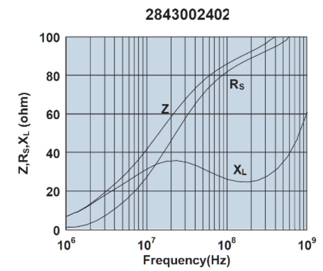
Above is the ReturnLoss plot of the trap very loosely coupled to the AA-600.

Of course this technique will not work on a trap that is substantially enclosed in a shield that prevents magnetic coupling. Note also that many traps used in ham antennas are simply a coil wound on an insulating rod and each end connected to the adjacent tubing, possibly with an overall aluminium tube that may or may not be bonded to the element tube at one end. The latter really become part of the element and measurement separate to the element is not simply translated to in-situ.

Equivalent circuit / simulation

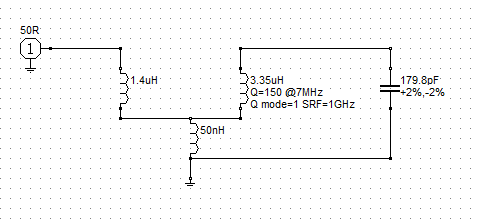
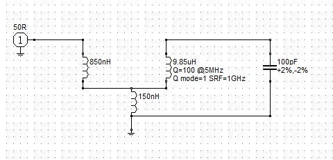
The inductor has previously been carefully measured to be 3.4µH. We can calibrate a model of the coupled coils to the observed resonant frequency and ReturnLoss.

Above, the equivalent circuit. We can calculate the flux coupling factor k from the model, it is 2.3% so this is very loosely coupled to avoid pulling the resonant frequency high.

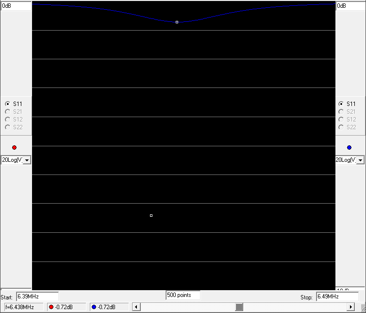
Above is the simulated ReturnLoss response over the same frequency range as measured.

Conclusions

It is practical to measure the resonant frequency of a trap by loosely inductively coupling an antenna analyser, depending on the structure of the trap and the capability of the analyser.

Practical measurements can be explained with a theoretical model of the measurement setup.

Measuring trap resonant frequency with an antenna analyser

Finding the resonant frequency of a resonant circuit such as an antenna trap is usually done by coupling a source and power sensor very loosely to the circuit.

A modern solution is an antenna analyser or one port VNA, it provides both the source and the response measurement from one coax connector.

Above is a diagram from the Rigexpert AA35Zoom manual showing at the left a link (to be connected the analyser) and the trap (here made with coaxial cable.

The advantage of this method is that no wire attachments are needed on the device under test, and that coupling of the test instrument is usually easily optimised.

Why / how does it work?

So, what is happening here? Lets create an equivalent circuit of a similar 1t coil and a solenoid with resonating capacitor.

The two coupled coils can be represented by an equivalent circuit that is derived from the two inductances and their mutual inductance. The circuit above represents a 1µH coil and a 10µH coil that are coupled such that 3% of the flux of 5% of the flux of one coil cuts the other (they are quite loosely coupled, as in the pic above. Continue reading Measuring trap resonant frequency with an antenna analyser

Choosing a toroidal magnetic core – ID and OD

One sees lots of articles describing inductors and transformers wound on rectangular cross section ferrite cores, and in explanations, the OD seems to be an important parameter but little consideration is given to ID.

Inductance of an inductor on a rectangular toroidal core depends on many factors, and among them ID and OD. Inductance is proportional to ln(OD/ID).

Above is a plot of the factor ln(OD/ID) against ID/OD as a percentage. It can be seen that for ID/OD approaching unity (ie a radially ‘thin’ toroidal core) that the characteristic is almost linear, and inductance is proportional to the radial thickness of the core. Continue reading Choosing a toroidal magnetic core – ID and OD

VU3SQM directional wattmeter build – #4

VU3SQM directional wattmeter build – #1 laid out the first steps in design review and build of a directional wattmeter.

At long last, some PTFE rod arrived to permit assembly of the transformers.

For reasons discussed in an earlier article, the transformers use a larger core than the original VU3SQM. They need to stand above the board, and whilst that compromises the mechanical strength of the assembly, it should have better performance. Continue reading VU3SQM directional wattmeter build – #4

VU3SQM directional wattmeter build – #3

VU3SQM directional wattmeter build – #1 laid out the first steps in design review and build of a directional wattmeter.

The parts have arrived and construction commenced.

Above, the PCB populated with the SM parts and soldered. It was soldered in an IR reflow oven. Continue reading VU3SQM directional wattmeter build – #3

VU3SQM directional wattmeter build – #2

VU3SQM directional wattmeter build – #1 laid out the first steps in design review and build of a directional wattmeter.

This article canvasses the issues of the display.

Intention is a digital based display (though not to exclude an analogue meter or bar graph type displays).

So, the output of the AD8307 needs to be digitised.

Let’s first consider the nature of the AD8307.

It is a log detector, so it provides a ‘DC’ voltage proportional to the log of the input signal, but the ‘DC’ voltage can vary very quickly.

The chart above from the AD8307 datasheet shows that the unfiltered response to a burst of RF has a rise time of well under 1µs. Continue reading VU3SQM directional wattmeter build – #2

VU3SQM directional wattmeter build – #1

VU3SQM offers an interesting directional coupler based on a Sontheimer coupler, and using AD8307 power sensing for a nominally HF coupler. I must say that I am not a fan of Sontheimer couplers… but that is what the board uses.

This article lays out a preliminary design review to assist in selection of appropriate toroids, and ordering of the needed parts.

PCB

Above, the top side of a PCB. Continue reading VU3SQM directional wattmeter build – #1