Fox flasher MkII – high power 2 LED solar powered beacon

Fox flasher MkII – owenduffy.net described an animal deterrent based on an STC 8051 microcontroller and running from a single LiPo cell.

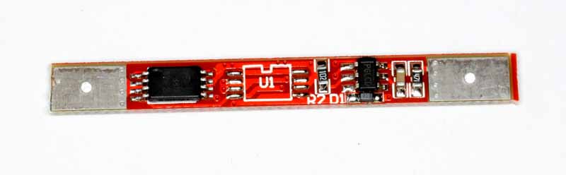
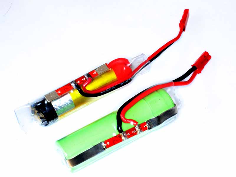
This article describes a further development using a solar cell, shunt regulator, 1S LiPo cell with protection board, and two high power red LEDs.

FF100
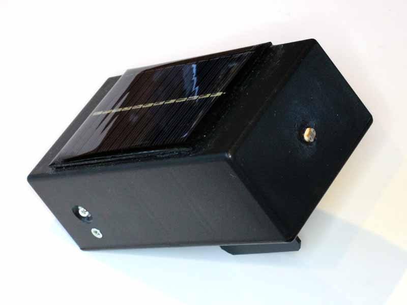
Above, the unit constructed in a medium size Jiffy box, and a 6V 0.6W PV panel fixed to the top with silicone adhesive. The LDR is fixed to one end with silicone adhesive.

Two SM 1W red LEDs are fitted to opposite sides. They are 120° LEDs, the holes are countersunk to provide for light dispersion and the LEDs clamped to the inside with small brass brackets and heat sink rubber, a little silicone adhesive seals the holes. Continue reading Fox flasher MkII – high power 2 LED solar powered beacon

PIK

This article describes a build of the PIC Iambic Keyer (PIK).

Screenshot - 18_04_16 , 19_47_22

Above is the generic circuit diagram of the PIK.

This one runs on 4.5V from 3 x AA cells. A 3000mAh battery will run it in ‘sleep’ mode for around 2,000,000 hours or 230 years… the shelf life of the batteries determines their useful life and there is consequently no ON/OFF switch.

So, the variation to the circuit above is that the zener regulator circuit is not required, Z1 is omitted and R5 is replaced by a 50mA Polyfuse. C3 is 0.0068µF to give a range of 6-36WPM on 4.5V.

PIK201

Above, the internals. The electronics is assembled on a small piece of Veroboard with jacks at the rear for paddle, hand key and output, a pot for speed control and switches for TUNE and AutoSpace.

PIK202

Above is the external view of the keyer prior to labelling.


Making sense of LED output figures

Browsing eBay for some high power LEDs for a current project created frustration in trying to wade through the stated performance figures (to they extent that they can be relied upon).

LEDs are often headlined as having some luminous intensity in candelas, but while that might seem to be a good measure of the ‘brightness’ of the LED viewed on-axis, it gives no information about the spatial distribution off-axis and the total luminous flux output or flux density.

I wrote a little online calculator that can be of assistance in finding the total luminous flux and flux density give luminous intensity and apex angle, Calculate luminous flux (lm) from luminous intensity (cd) and apex angle (°). (Note that specified luminous intensity is usually on axis and should be discounted by perhaps 20% to provide an average luminous intensity over the cone angle.)

Example 1

An example, an eBay seller advertises:

Specifications:
Source Material: InGaN !
Emitting Colour: 0.5W 10MM HI POWER White 0.5W LED
LENS Type: Water clear
Luminous Intensity-MCD: Typ: 290,000 mcd
Reverse Voltage: 5.0 V
DC Forward Voltage: 3.2 ~ 3.4V
DC Forward Current: 100mA
Viewing Angle: 40 degree
Lead Soldering Temp: 260¡ãC for 5 seconds
Power Dissipation: 500mW

Does it appear rational? Lets calculate average luminous intensity at 80% of 290cd, 232cd. Lets assume the viewing angle is the half power beamwidth.

Screenshot - 15_04_16 , 09_50_50

Above is a calculation from the specifications. Of concern is the calculated luminous efficiency of 266lm/W, it is perhaps three times or more the expected value, so it questions the accuracy of the claims. Even at 0.5W input, the luminous efficiency is unrealistically high. Continue reading Making sense of LED output figures

Red Ironbark picnic table

I made a couple of picnic tables about 35 years ago. The design was broadly inspired by picnic tables deployed by the ACT administration at the time (local government), it used a galvanised water pipe frame for table and integral seats and hardwood tops.

IMG_0484a

I kept one of these tables, and the hardwood eventually degraded sufficiently to warrant replacement.

Durable timber has become very expensive, and the choice limited. Red Ironbark (a eucalypt endemic to the forests south east of here), GOS (green off saw) and DAR (dressed all round) was chosen, and stacked in the shed for a couple of years to dry down to 10% moisture content.

The timber was washed down, trimmed and edged, drilled and oiled (Organoil, a naturally drying oil mix), and fixed to the table with 304 stainless countersunk socket head M8 screws and nyloc nuts.

PicnicTable

Above, the refurbished table. Total mass is 125kg, about half of that is in the hardwood and the rest in the steel frame.

The table will required replenishment of the oil finish every year, but should be a durable non-toxic lasting finish with that maintenance.

Lithium battery – 1S protection boards

Some of my projects use a single Lithium cell for power, and the ready availability of low-cost battery protection boards offers opportunity for better projects.

IMG_1472Above, a 1S board rated at 4A and which sells for about A$1 posted in lots of 5.

Specifications:

Description:
New and good quality
Use BM112 protection chip + AO8810 MOS tube
The protection board is used to protect the battery overcharge, over discharge, so can’t use as a charger,when you want to charge the battery you need to use the dedicated charger,because the protective board has a time to response to the short circuit, can’t to connect too large instant impact current, such as drills and so on

The main performance parameters:
1. PCB Size: 39 * 4 * 2mm
2. Overcharge protection voltage: 4.2750 ± 25MV
3. Over-discharge protection voltage: 2.88 ± 75MV
4. The overcurrent protection: 4-8A
5. Continue working current: > 4A

Note: Only for the equipment which instant start-up current less than 4A,those starting current instant is great, such as high-current motors, drills, etc., are not suitable for use.

IMG_1473

Above are protected battery assemblies based on the board and a 1200mAh LiPo (sells for about A$4) and Panasonic 18650 Li-ion 3400mAh (sells for about A$12). The connectors used are 3A rated JST RCY connectors as used in RC battery applications and readily available with tails for way less than A$1 each set.

The 18650 cell has tags spot welded to the battery contact points, the LiPo has contact tags as supplied.

To use these, the power source needs to supply about 4.5V so as to ensure charging when necessary. The power source needs to be current limited unless you choose to depend on the protection boar’s limit.

Panasonic NCR18650B Lithium Ion cells on eBay

Further to 18650 Lithium Ion cells on eBay I purchased a pair of Panasonic NCR18650B cells, nominal 3400mAh, from an Australian supplier for about A$22 posted.

NCR18650B

Above is a pic of a cell.

NCR18650B02

Above is a zoomed in view of the same pic with increased contrast. The feint QC code printed on the underlying steel container is visible. It is usually visible through the jacket on genuine Panasonic cells.

It is always hard to know whether the product is genuine, the Chinese are better at copying the looks than the internals.

The cell was charged, then discharged at 1C on a battery analyser.

Screenshot - 15_01_16 , 03_12_18

Above is the first three discharge cycles, the cell achieved just under 3000mAh to 2.8V, about 93% of datasheet rated capacity of 3200mAH, 85% of the advertised nominal 3400mAh capacity.

Screenshot - 14_01_16 , 18_39_55

The actual discharge curve is fairly similar to the 1C curve from the datasheet.

These cells look more promising than the GTL red 5300mAh cells previously evaluated.

18650 Lithium Ion cells on eBay

I have been intrigued by the huge number of sellers of very low cost 18650 Li-ion cells on eBay.

Could they be any good?

As a reality check, Panasonic cells around 3000mAh sell through traditional channels here in Australia for around A$20 per cell, there are Australian eBay sellers selling cells advertised as Panasonic for around A$22 per pair posted.

GTL01Above, the GTL red LS18650 5300mAh Li-ion cell purchased in a lot of five for $1.30 each (inc post from China).  The rated capacity is more than 50% higher than the maximum from brand name products. Continue reading 18650 Lithium Ion cells on eBay

Revised thinking on STC chips

I have successfully implemented a few projects on the STC 15F104E, a Chinese 8051 architecture MCU.

STC15fF04EThe chip includes EEPROM, and some flexible extensions to the timers which potentially make it more useful than a standard 8051.

I have previously observed that the documentation is poor, and the programming tool is poor.

The project that led to the latest observations was an attempt to implement RC PWM – ON/OFF switch originally on one of these chips as it contained sufficient resources to suit the application. One of those resources was an +/- edge triggered INT0.

The code worked fine, but for only a short and variable period. Essentially, the the main loop was executing fine, the chip stopped triggering the interrupt service routing for INT0 after a variable time from 10s to 1000s… but it ALWAYS stopped working. Cycle the power and the same thing is observed. Continue reading Revised thinking on STC chips

RC PWM – ON/OFF switch

This article describes a remote ON/OFF switch which uses an RC receiver and adapter chip to convert the RC PWM signal into an ON/OFF output. (Suitable RC transmitters are on hand.)

The immediate application is for remote ON/OFF PTT or KEY of a transmitter for field strength testing at various locations.

Background

Remote control hobbies have long used a multi channel digital proportional protocol for control of planes etc. The simplest multi channel receiver has an independent PWM output for each servo.

The PWM signal is a 1000-2000µs pulse with a repetition rate from about 50Hz up to 500Hz or so, the duration of the pulse conveys the information.

Implementation

The converter chip is a ATTiny25 MCU with firmware that monitors the PWM stream and provides ON/OFF and OFF/ON output pins. For the immediate application, the ON/OFF (or non inverted) output drives a 2N7000 FET with ‘open collector’ output suited to the PTT and KEY lines of most modern transceivers.

The firmware ignores PWM signals with duration outside the range 900µs to 2100µs, and switches ON at 1600µs, and OFF at 1400µs to provide some hysteresis. If PWM input is lost for 125ms, the output will fail safe OFF.

rcsw01Above is the schematic. The 2N7000 is good for 60V, can handle up to 100mA without a heat sink, and had a body diode to absorb transients if the load is a relay. Continue reading RC PWM – ON/OFF switch

Trial of prototype stand alone GPS logger

An upcoming project calls for a stand alone GPS logger.

The requirement is for a GPS stream that allows correction using RTKLIB, but this trial is of a lesser GPS as proof of concept.

SAGPS001

Above, the equipment consists here of a Ublox NEO-6M based GPS module (~A$15 incl on eBay) at left, an Openlogger (~A$15 incl post on eBay) at right, and a 12V-5V converter (~A$7 from Hobbyking) at bottom. The latter is a 5A converter, way overkill, but it was on hand. The GPS module has a 3V regulator on board for the NEO-6M chip.
Continue reading Trial of prototype stand alone GPS logger