Exploiting your antenna analyser #18

Measure velocity factor of open wire line

One of the measurement tasks that one often encounters is to measure the velocity factor of a transmission line.

Often this is an indirect task of tuning a tuned line section, my method is to often measure some line off the role, find the velocity factor (vf), and use that to cut line for the tuned section making appropriate allowance for connectors etc.

Measuring vf for an open wire line includes all that is done for measuring vf of coax, but requires measures to ensure that common mode current does not affect measurement significantly.

To minimise common mode current effects, I will use two measures:

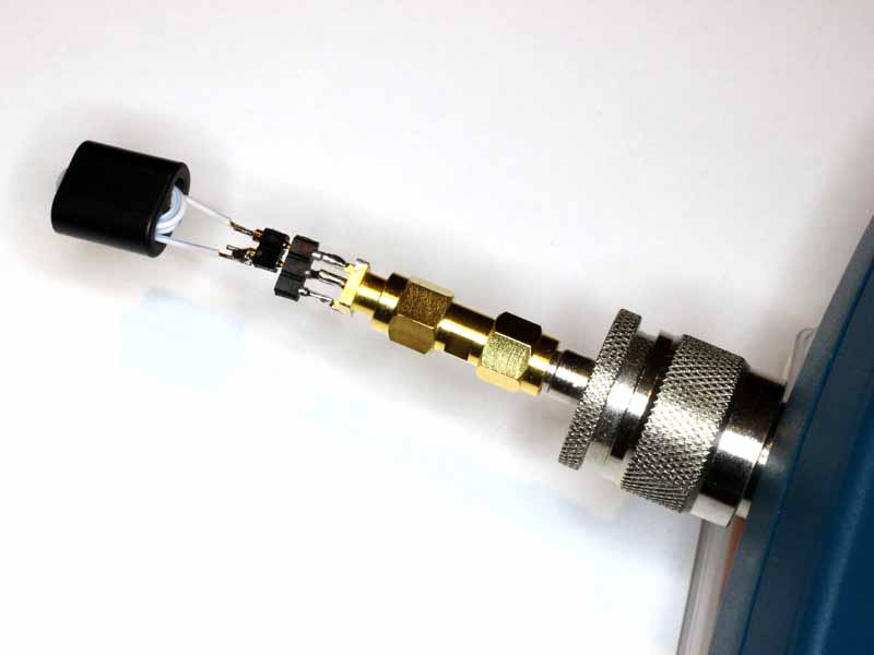
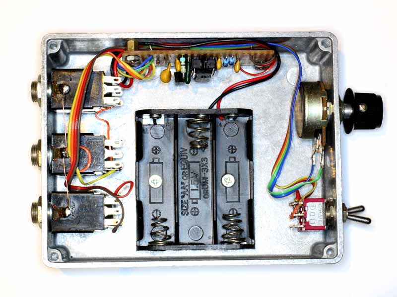
  • a high common mode impedance Guanella balun; and
  • form the line section being measured into a loose helix supported on some fishing line to spoil any common mode resonance.

Aa600BalunRg316

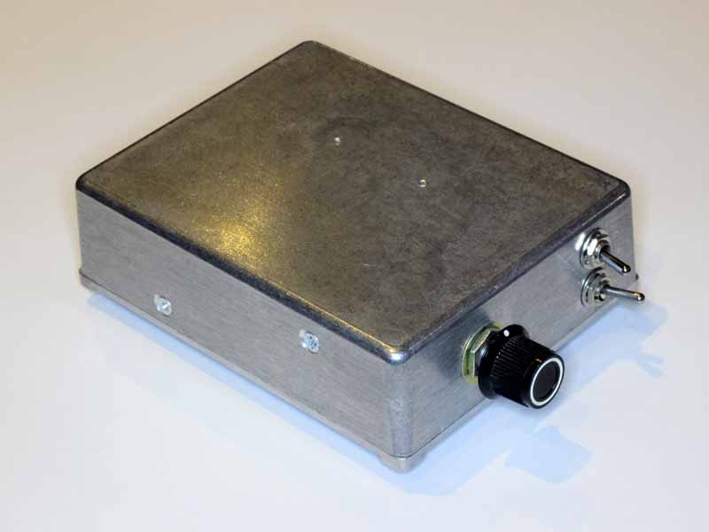
Above is the balun used, it is described at Low power Guanella 1:1 balun with low Insertion VSWR using a pair of Jaycar LF1260 suppression sleeves. Continue reading Exploiting your antenna analyser #18

Exploiting your antenna analyser #17

Optimising a G5RV with hybrid feed

(Varney 1958) described his G5RV antenna in two forms, one with tuned feeders, and the more popular form with hybrid feed consisting of a so-called matching section of open wire line and then an arbitrary length of lower Z0 coax or twin to the transmitter.

(Duffy 2005) showed that the hybrid feed configuration is susceptible to high losses in the low Z0 line as it is often longish, is relatively high loss line and operates with standing waves. Varney did offer two options for the low Z0 line: any length 72Ω twin or coax. Continue reading Exploiting your antenna analyser #17

Exploiting your antenna analyser #16

Measure inductor using SOL calibration

At Measuring balun common mode impedance I showed a method of backing out the effects of a text fixture using the “subtract cable” facility of Antscope software with the Rigexpert AA-600.

Some analysers (including the AA-600) support SOL calibration of the instrument itself, and some support SOL calibration using the client software (Antscope in this case). This article demonstrates use of Antscope with SOL calibration to measure a small RF inductor which has similar characteristic to good Guanella 1:1 HF baluns.

The text fixture used for this demonstration is constructed on a SMA(F) PCB connector using some machined pin connector strip, and SMA(M)-SMA(M) and N(M)-SMA(F) adapters to connect to the AA-600.

Aa600Fix02

Above is a pic of the test inductor in the test fixture with adapters. The test inductor 6 turns of 0.5mm PVC insulated wire wound on a BN43-202 binocular balun core. Continue reading Exploiting your antenna analyser #16

Improved cooling for the ATR-30

In Improved cooling for the MFJ-949E I described a solution to a problem of demonstrated overheating of the ATU at rated power, indeed at a lot less than rated power.

Though I have never measured the ATR-30 temperature rise, and am probably unlikely to stress the 3kW rated ATU with a 100W transmitter, I have performed a similar cooling modification to the ATR-30.

Continue reading Improved cooling for the ATR-30

Exploiting your antenna analyser #15

Measure MLL using the half ReturnLoss method – a spot test with a hand held analyser

At Exploiting your antenna analyser #14 I gave an explanation of the method of approximating MLL of a line section by taking the average half Return Loss with o/c and s/c terminations.

This article demonstrates the technique using the Rigexpert AA-600 analyser in hand held mode.

The task is to assess whether a section of RG58A/U coax has MLL at 3.5MHz similar to specification or not.

The specification loss of 10.13m of RG58A/U has MLL=0.29dB.

HRL01

Above, the first test with an o/c termination. Return Loss is 0.4dB. Continue reading Exploiting your antenna analyser #15

Assessing the Q of a half wave dipole antenna system – a real world example

Assessing the Q of a half wave dipole antenna system explained that Q can be a valuable indicator of antenna system health.

This article uses a recently published VSWR curve for a 15m half wave dipole antenna system as an example to demonstrate the technique.

The following graph is from a Sark100 style antenna analyser, and it is quite a poor start to diagnostics, but using it draws out what is desired for further analysis.

Vswr15m

Above, the captured VSWR50 sweep. Continue reading Assessing the Q of a half wave dipole antenna system – a real world example

Assessing the Q of a half wave dipole antenna system

Q can be a valuable indicator of antenna system health

The Q of an antenna can be a useful statistic in assessing whether it is operating as it should.

The Q of half wave dipole antenna system on HF depends to some extent on conductor size, its environment (height, type of ground, nearby structures and vegetation, and feed line / matching loss. Nevertheless, it should usually fall in the range of 10 to 13 for good wire dipoles, and if you measure a half wave dipole antenna system to have Q significantly outside that range, it is probably significantly less efficient than it should be. Continue reading Assessing the Q of a half wave dipole antenna system

PIK

This article describes a build of the PIC Iambic Keyer (PIK).

Screenshot - 18_04_16 , 19_47_22

Above is the generic circuit diagram of the PIK.

This one runs on 4.5V from 3 x AA cells. A 3000mAh battery will run it in ‘sleep’ mode for around 2,000,000 hours or 230 years… the shelf life of the batteries determines their useful life and there is consequently no ON/OFF switch.

So, the variation to the circuit above is that the zener regulator circuit is not required, Z1 is omitted and R5 is replaced by a 50mA Polyfuse. C3 is 0.0068µF to give a range of 6-36WPM on 4.5V.

PIK201

Above, the internals. The electronics is assembled on a small piece of Veroboard with jacks at the rear for paddle, hand key and output, a pot for speed control and switches for TUNE and AutoSpace.

PIK202

Above is the external view of the keyer prior to labelling.


A tale of three tuners

At HC-500 I showed some VNA plots of the HC-500 matching a 50+j0Ω load at 3.5MHz.

The following commentary is on a single load scenario, a 50+j0Ω load at 3.5MHz, and while the results are not simply extensible to other loads and frequencies, it does provide some interesting insight into the devices.

THP HC-500 (Ultimate Transmatch (McCoy 1970))

Screenshot - 13_04_16 , 08_06_08

Above is the behaviour of the unmodified HC-500 (an Ultimate Transmatch).

Losses at match are 12% of input power. At its rated 500W maximum power, that is 60W (which might seem high but heat tolerant insulation materials are used). On modification to a T match, losses at match were reduced to 8% or 40W at rated maximum power.
Continue reading A tale of three tuners

HC-500

In the early 1970s I purchased a Tokyo High Power Labs HC-500 ATU based on recommendation of other hams and the seller’s representations (Dick Smith Electronics) that it was a T match with 200pF capacitors.

The circuit configuration is of the so-called Ultimate Transmatch, an invention of (McCoy 1970) that claimed a bunch of advantages over the ordinary T match.

The HC-2500 would appear to use the same circuit.

It wasn’t long before several authors waded into the Ultimate Transmatch over its poorer efficiency. With an ambitious name like Ultimate Transmatch, it had a lot to live up to… but it failed.

Within months, a reconfigured topology appeared entitles the SPC Transmatch, but it also had issues.

The reality is that none of these designs is ‘ultimate’, they all have advantages and disadvantages and are mostly used in ignorance of those.

So, I have had this HC-500 which worked well enough I suppose, but was quite difficult to tune on some loads that ordinary T matches handled with ease. It has always been my intention to reconfigure it to a T match be rewiring the grounded stator of the input cap to parallel it with the other stator… a minimal modification to get rid of the shunt capacitor and use it to help to keep coil voltage down on some loads.

Before performing the modification, I measured transmission loss when matched to a 50+j0Ω load at 3.5MHz using a two port VNA.

Screenshot - 11_04_16 , 20_26_07

Above, transmission loss is 0.54dB, efficiency is 88.3%. Continue reading HC-500