An interesting case study of measurement of a balun’s Insertion VSWR

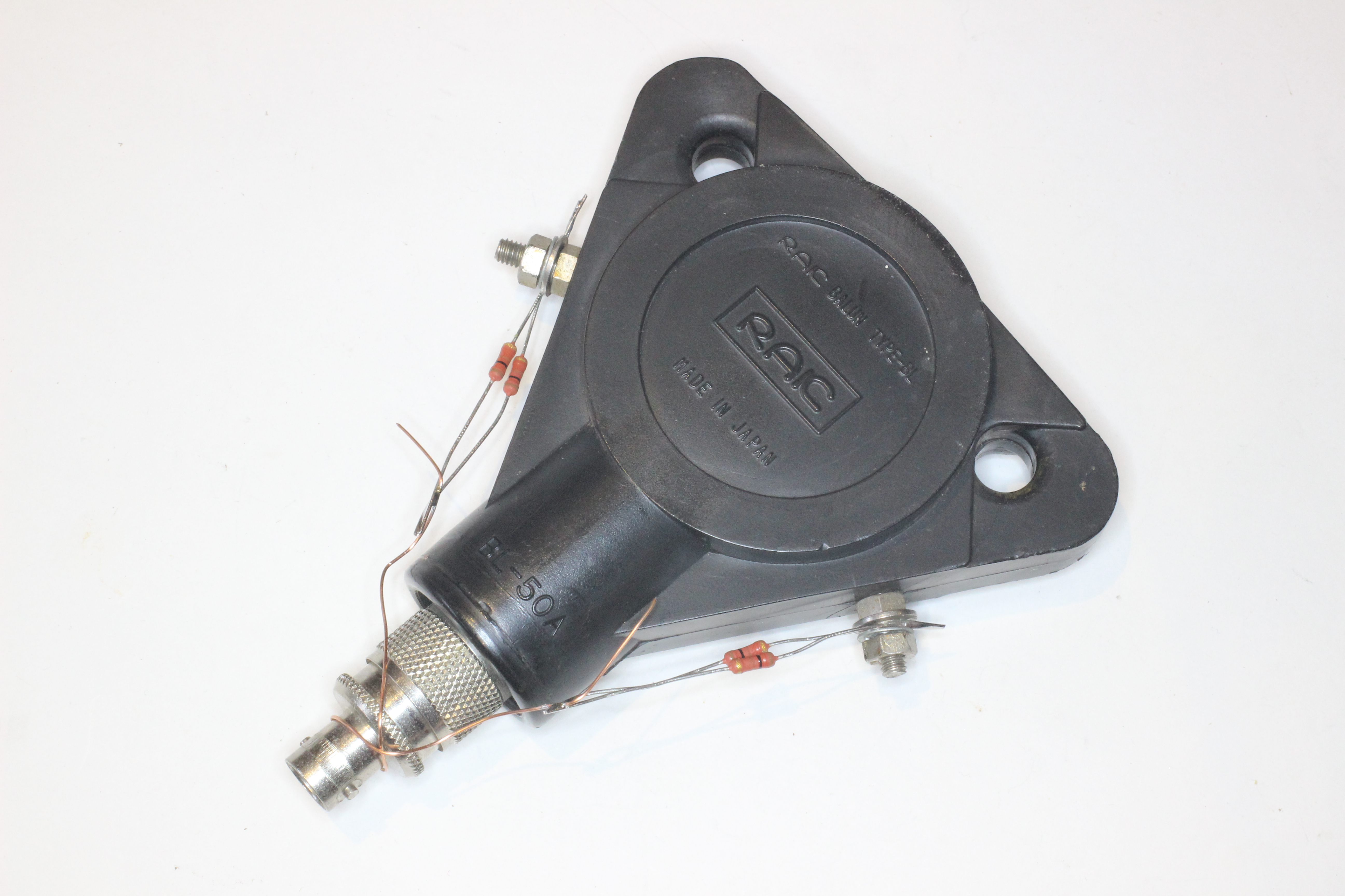
Jeff, 2E0CIT, sent me a Rigexpert AA-170 measurement file of his test of Insertion VSWR of a commercial balun.

Insertion VSWR is the VSWR looking into the balun with a matched load (termination) on its output, it is a measure of imperfection of the balun. It ought to be a specification item for low Insertion VSWR baluns, but it rarely given.

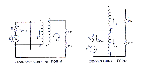
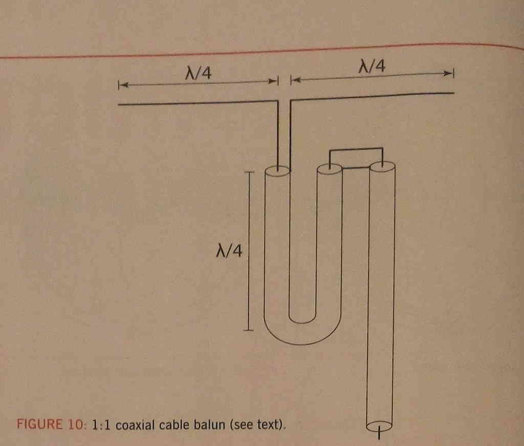
A broadband low Insertion VSWR balun must be wound with a transmission line of the nominal impedance, 50Ω in this case, and in the case of 50Ω , it is most likely to be coax.

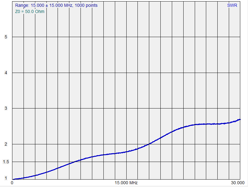
Above is the initial VSWR plot received. The VSWR response is poorer than one might want in a low Insertion VSWR balun… but to drill down on the reasons, the Smith chart view of the data gives insight. Continue reading An interesting case study of measurement of a balun’s Insertion VSWR

Choosing a toroidal magnetic core – ID and OD

One sees lots of articles describing inductors and transformers wound on rectangular cross section ferrite cores, and in explanations, the OD seems to be an important parameter but little consideration is given to ID.

Inductance of an inductor on a rectangular toroidal core depends on many factors, and among them ID and OD. Inductance is proportional to ln(OD/ID).

Above is a plot of the factor ln(OD/ID) against ID/OD as a percentage. It can be seen that for ID/OD approaching unity (ie a radially ‘thin’ toroidal core) that the characteristic is almost linear, and inductance is proportional to the radial thickness of the core. Continue reading Choosing a toroidal magnetic core – ID and OD

Voltage symmetry of practical Ruthroff 1:1 baluns

Well, I guess Voltage symmetry of practical Ruthroff 4:1 baluns begs the question, what about Ruthroff 1:1 voltage baluns?

The Ruthroff 1:1 voltage balun can be seen as two back to back Ruthroff 4:1 voltage baluns with the redundant winding removed… and that prompts the thinking that the cascade of two baluns back to front might cancel the phase delay.

Let’s measure a popular Ruthroff 1:1 voltage balun.

RAK BL-50A

Above, the RAK BL-50A was a quite popular balun, and probably the balun of choice for half wave dipoles… well until the message about current baluns escaped. Continue reading Voltage symmetry of practical Ruthroff 1:1 baluns

Voltage symmetry of practical Ruthroff 4:1 baluns

Much is written about antenna system balance, this article looks at balance issues with the very common ATU configuration that uses a Ruthroff 4:1 voltage balun to adapt coax transmitter output to two wire open feed line. This type of balun is employed in most ham market ATUs that contain an integral balun.

Above is Ruthroff’s equivalent circuit, Fig 3 from his paper (Ruthroff 1959).

If one looks carefully at the transmission line form, there is effectively a two wire line wound into a helix (usually on a magnetic core) and connected from the unbalanced source to one half of the load inverting the connection for the necessary phase reversal.

Ideally, Vout of this line is equal to Vin, ie Vout/Vin should be 1∠0°. That is unlikely as it implies a zero length transmission line which provides the decoupling of the phase inverting line.

This article looks at the Ruthroff 4:1 balun balance using the very popular MFJ-949E as an example.

Above is a pic of the MFJ-949E Ruthroff 4:1 balun. The transmission line is not uniform, but let’s make an approximation to predict its behavior with a centre tapped 100Ω load, the centre of which is connected to the ground terminal. Continue reading Voltage symmetry of practical Ruthroff 4:1 baluns

Radcom Feb 2019 “cable balun” – a deeper look

This article is a continuing discussion of Radcom Feb 2019 “cable balun”.

The article Baluns in antenna systems explores some different dipole and feed line configurations and the effectiveness of common mode chokes at various locations on the feed line.

Models 1, 2 and 3 particularly show the effect of a quarter wave vertical common mode conductor grounded and isolated, and a half wave vertical common mode conductor grounded.

These illustrate that those common mode conductors can be viewed to some extent as a ‘single wire’ transmission line, and the impedance presented at the dipole feed point is low or high in keeping with simple transmission line analysis of a shorted or open line of quarter or half wave length.

The question then arises with the Radcom “cable balun”, does it behave similarly, to what extent does the folding of the conductor affect its quarter wave resonance.

NEC models

One way to explore this is to construct an NEC model of the structure and a reflection of itself.

Three quarter wavelength a side folded

Above is the serpentine structure of three quarter wavelength folded, and below it, a reflection of itself. The whole structure is fed in the middle and the impedance vs frequency charted. Continue reading Radcom Feb 2019 “cable balun” – a deeper look

Radcom Feb 2019 “cable balun”

A correspondent asked for an explanation of a novel balun described in Radcom Feb 2019 by K3MT.

Above is a diagram of the so-called “cable balun”.

To evaluate it, I have inserted it into one of the NEC models used for the article Baluns in antenna systems, the model used for Model 3 which I will repeat here for convenience. Continue reading Radcom Feb 2019 “cable balun”

Rigexpert’s Antscope takes a bigger step backwards

At Rigexpert’s Antscope takes a step backwards I wrote of Rigexpert’s determination to cripple Antscope by reducing the maximum value of R and X on graph axes to +/- 1600Ω.

I have deferred trying the new Antscope2 until now to allow it to reach some maturity.

This article is a brief review of Antscope2 v1.0.10, brevity driven by the need to cut losses and run.

The first thing I noted is the difficulty in reading some textual data due to low contrast. The mid blue on mid grey above is very hard to read and would be even harder outdoors if measurements were being made in that environment. I did not search for alternative themes, none jumped out, but out of the box, this is very limiting. FAIL. Continue reading Rigexpert’s Antscope takes a bigger step backwards

Is |s21| measurement of a common mode choke meaningful to antenna systems?

A common theme among online experts is to measure, or ask for measurement of a common mode choke connected between the centre conductor of a VNA’s tx and rx ports. That raises the question of whether |s21| with both ends shorted is meaningful, whether it in any useful way characterises the choke as a component of an antenna system.

Direct measurement of common mode current is not difficult, and it is almost always the best way to determine the effect of a choke on common mode current.

That said, analytical and simulation techniques can be of great value in the antenna design process, well before a prototype antenna is built.

An example choke at 7MHz

Lets perform an experiment using NEC to model the effect of a choke in a 7MHz antenna.

The choke used uses 11t on a FT-240-43 ferrite core. The values are from a calibrated model, values confirmed by measurement.

We will use NEC-4.2 with one of the scenarios detailed in the article Baluns in antenna systems, Model 4, but using the choke described above which has an impedance of 3175+j2502Ω at 7MHz.

Above is a simulation of the connection. Zcm of the choke in this case at 7MHz, 3175+j2502Ω, has been converted to an equivalent inductance and resistance to suit the simulator. (Note that the equivalent circuit it valid only for a narrow band, there is no simple wideband circuit equivalent for this ferrite cored choke (more later).) Continue reading Is |s21| measurement of a common mode choke meaningful to antenna systems?

Discussion of WA7ARK’s contribution to a QRZ thread on an End Fed Dipole

In another long running discussion on QRZ about End Fed Antennas, WA7ARK offered a contribution:

(1) Back in post #30 I showed that with a halfwave wire fed close to its end works just like the same wire fed in the center; the only difference being the feed point impedance. I let EzNec figure this out; I didn’t have to explain it with any mysterious “displacement” currents. Shown as (1) in the attached.

Since, in the model, the source is a constant current source, that forces the current on either side of the source to be equal, and the radiation pattern predicted by EzNec reflects that, because the patterns for the end-fed and center-fed match… (go back and look at post #30)

His post #30 is of a 67′ dipole at 66′ above poor ground @ 7.18MHz, fed at one end.

Above is the current distribution of my approximate re-creation of his model in NEC-4.2. It reconciles with his published graphs. Continue reading Discussion of WA7ARK’s contribution to a QRZ thread on an End Fed Dipole

woolly thinking on the nature of feed line common mode current

An online expert somewhat exasperated that the audience hasn’t absorbed his wisdom elaborated in apparently many previous posts said:

We’ve been round and round on this discussion but in a current mode balun aka a common mode choke the losses due to the windings and core are common mode not differential mode losses. You DO NOT dissipate your transmitted and received signals, which are carried as differential mode signals, as choke losses.

I know you’ve been reminded of this many times and don’t expect you to accept it now but that’s how common mode chokes work.

Now there is a sense in ham radio forums that repetition transforms assertions to fact, but setting that aside, let’s look at the assertion from an energy conservation point of view. Continue reading woolly thinking on the nature of feed line common mode current