Hams embrace the UHF series connectors like no one else, including for its use on test equipment where its performance is lacking.
This is the likely reason why it is so hard to find low VSWR 50Ω terminations with UHF series plug. It is rare to find something with VSWR quoted in specifications, and nigh on impossible to find one at a reasonably low price.
On the other hand, SMA terminations start at about $2 each (posted), and it is not too hard to find ones specified with VSWR<1.2 to several GHz.
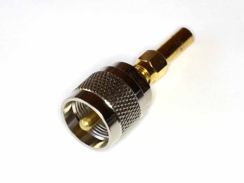
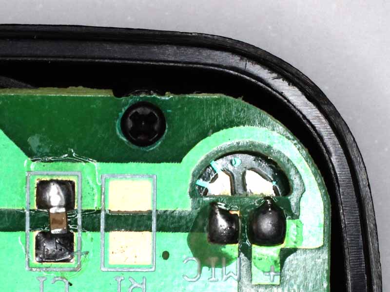
Above is a low cost, low quality solution. It is a SMA termination selected from a bunch using a high accuracy DMM (selected, R is 49.86Ω) and a SMA(F)-UHF(M) adapter, total cost $7 (posted) (but you might be advised to buy 5 loads to select the best one). Despite the specification, they are probably only good to 100MHz, and can be unreliable. Continue reading A check load for antenna analysers with UHF series socket