Designing high performance VHF/UHF receive systems – Part 5

Bringing it all together

This part explains how to build a model of the entire receive system to calculate G/T.

Firstly, make an inventory of all of the system elements that you intend to model.

A model needs to be no more detailed than is necessary to provide adequate accuracy for the purpose at hand.

Continue reading Designing high performance VHF/UHF receive systems – Part 5

ARRL Test Procedures Manual (Rev L) – Noise Figure calculation

(Allison et al 2011) detail the method used by the ARRL in their test reports on equipment.

Effectively they calculate NF=-174+27-MDS where MDS is measured in the CW mode using the 500 Hz, or closest available IF filter (or audio filters where IF filters are not available).

One flaw in this method is that the factor 27dB in the NF formula implies that the Equivalent Rectangular Bandwidth (ERB) of the receiver when measuring MDS is exactly 500Hz. More correctly, the formula should be NF=-174+10*log(ERB)-MDS. The error could be significant, especially with the closest available…  provision in the test requirement.

Clip 159

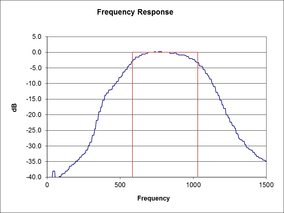
For example, above is the measured IF response of a TS-2000 set to 500Hz bandwidth. As filter responses go, it is very good, having quite a flat region, better than most crystal filters used for CW, but the ERB is actually 430Hz, that is 0.66dB less noise than a 500Hz ERB filter and any NF based on 500Hz is low by 0.66dB.

The red plot is that of an idealised filter of the same ERB.

Clip 157The plot above is for an R-5000 with 500Hz crystal filter. ERB is 446Hz, 0.5dB lower than the nominal 500Hz bandwidth which would lead to an error of 0.50dB using the ARRL’s method for estimating NF.

A more fundamental flaw is  uncertainty in measured MDS leads to a relatively large uncertainty in NF when NF is small. The test reports do not specify the uncertainty of MDS, it is unlikely (Duffy 2007), (Duffy 2007b) that with receiver bandwidth of 500Hz (as specified for the MDS test) and the HP339A instrument used, that uncertainty to 95% confidence level is as low as ±0.5dB probably closer to ±1dB. The method used is just not suitable to low noise receivers.

Giving NF rounded to 1dB is not very informative for receivers with NF below 5dB, and fairly useless at 2dB as in (Wilson 2012).

References

  • Allison, B; Tracy, , M; Gruber, M. 2011. Test Procedures Manual Rev L. ARRL Newington.
  • Duffy, O. 2007. Uncertainty of the noise sampling process. https://www.owenduffy.net/files/NoiseMeasurementUncertainty.pdf .
  • ———. 2007b. Noise measurement uncertainty calculator. VK1OD.net (offline).
  • ———. 2014. ARRL Test Procedures Manual (Rev L) – Noise Floor test. https://owenduffy.net/blog/?p=1165 (accessed 15/03/2014).
  • Wilson, M. 2012 ICOM IC-9100
    MF/HF/VHF/UHF Transceiver In QST Apr 2012.

Designing high performance VHF/UHF receive systems – Part 4

Finding transceiver Teq

We have explained how to calculate Teq from Noise Figure, but most transceiver specifications do not give Teq or Noise Figure directly, in fact they don’t really contain sufficient information to reliably calculate Teq or Noise Figure.

Credible equipment reviews might provide an estimate of Noise Figure or Teq.

The best approach is to directly measure Noise Figure using a known noise generator and the Y Factor Method.

Continue reading Designing high performance VHF/UHF receive systems – Part 4

Designing high performance VHF/UHF receive systems – Part 3

Relationship between Teq and Noise Figure

In the last part, the meaning of the equivalent noise temperature of an amplifier was given.

Whilst you will find that working in Teq has advantages for this analysis, amplifier specifications may not give Teq, but may give Noise Figure.

Continue reading Designing high performance VHF/UHF receive systems – Part 3

Designing high performance VHF/UHF receive systems – Part 2

G/T is defined as the ratio of antenna gain to total equivalent noise temperature.

For clarity, lets define those terms.

Gain

Gain of an antenna is defined (IEEE 1983) as the ratio of the radiation intensity, in a given direction, to the radiation intensity that would be obtained if the power accepted by the antenna were radiated isotropically. (Isotropically simply means equally in all directions.)

Continue reading Designing high performance VHF/UHF receive systems – Part 2

Designing high performance VHF/UHF receive systems – Part 1

G/T

A metric that may be used to express the performance of an entire receive system is the ratio of antenna gain to total equivalent noise temperature, usually expressed in deciBels as dB/K. G/T is widely used in design and specification of satellite communications systems.

G/T=AntennaGain/TotalNoiseTemperature 1/K

Example: if AntennaGain=50 and TotalNoiseTemperature=120K, then G/T=50/120=0.416 1/K or -3.8 dB/K.

Continue reading Designing high performance VHF/UHF receive systems – Part 1

VK2OMD ambient noise measurement 144MHz – 20140217

I made a measurement of ambient noise on 144MHz this morning using the technique described at (Duffy 2009).


TS2000NF

First step is to recheck the NF of the receiver. The TS2000 is getting a little tired, NF=8.3dB.

The technique calculates ambient noise from the variation in receiver output noise of a receiver of known Noise Figure with the insertion of a known input attenuator. The receiver output noise was measured using NFM (Duffy 2007) which allowed integration over 20s for high resolution measurement.

046 Continue reading VK2OMD ambient noise measurement 144MHz – 20140217