Antennas – disturbing the thing being measured – open wire lines #5

The articles Antennas – disturbing the thing being measured – open wire lines #3 Antennas – disturbing the thing being measured – open wire lines #4 demonstrated an inconsistency between a partial linear circuit model and a complete NEC model for predicting common mode current behaviour.

One of the oft proposed solutions to characterising a balun is to find the Common Mode Rejection Ratio (a term carried over from other applications, eg voltage driven operational amplifiers). (Anaren 2005) explains a method of finding balun CMRR.  (Skelton 2010) goes so far as to say

The Common Mode Rejection Ratio (CMRR) of a balun is defined in professional literature as the ratio of wanted to un-wanted transmitted power. As rejection of common-mode transmission is the primary purpose of a balun, it follows that CMRR should be the key figure of merit.

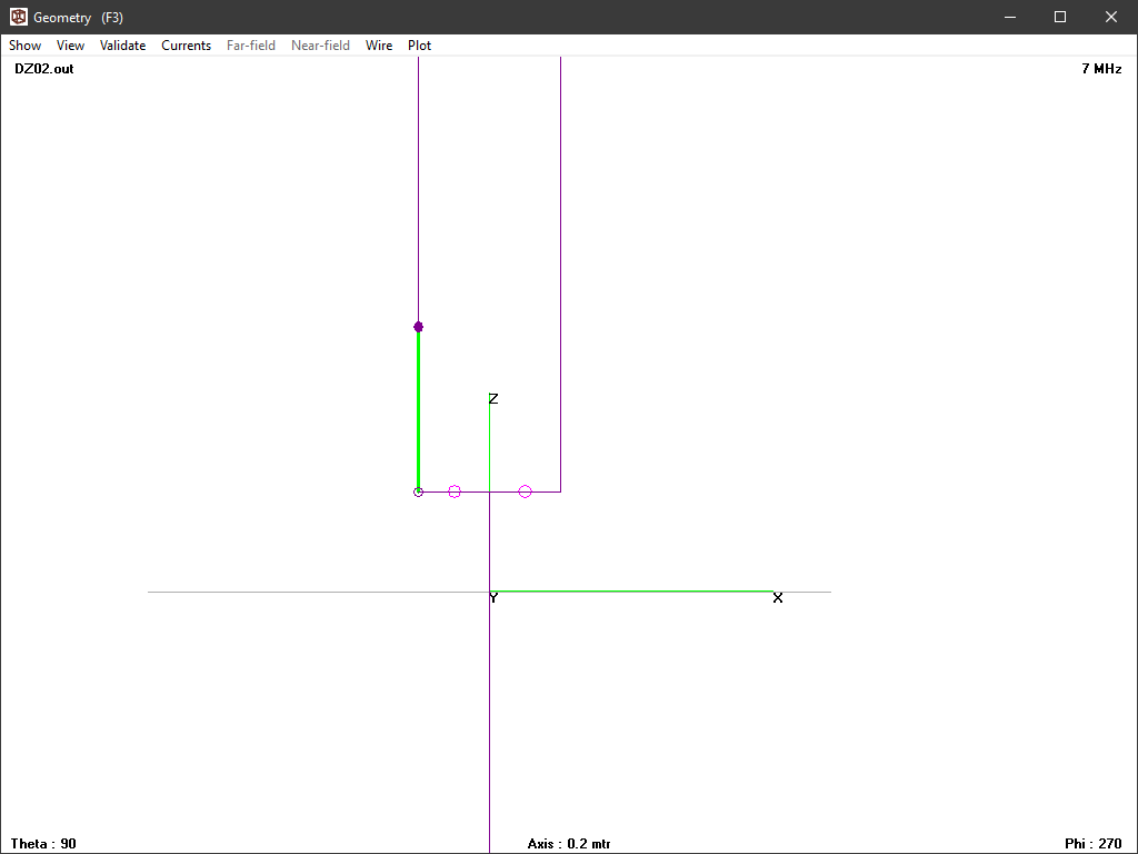
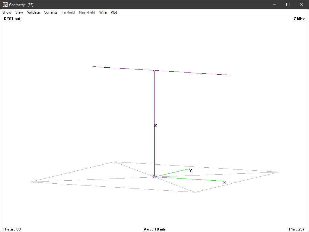
Let us take the model scenario used in Antennas – disturbing the thing being measured – open wire lines #4 and lower the height of the dipole 10 10m, and compare the model ratio of Ic/Id.

Again, we will use Python to do the complex maths for the without and with scenarios at 20m height, and without and with at 10m height. Continue reading Antennas – disturbing the thing being measured – open wire lines #5

Antennas – disturbing the thing being measured – open wire lines #4

The article Antennas – disturbing the thing being measured – open wire lines #2 did a simple analysis of current flows in the model scenario using ideal voltage balun drive with a current balun.

It was mentioned that solution of the lumped values network is only a first approximation and not as good as the NEC solution which properly models the coupled conductors, and their mutual effect on the distribution of currents in the system.

This article reports the NEC current solution decomposed into differential mode and common mode components.

Ideal voltage balun drive

Above is a zoomed in view of the feed point with a balanced pair of voltage sources feeding the line against the ground electrode. Continue reading Antennas – disturbing the thing being measured – open wire lines #4

nanoVNA-H – measure 40m low pass filter for WSPRlite flex

This article demonstrates the use of a nanoVNA-H to measure the response of a low pass filter designed to pass 7MHz frequencies but attenuate harmonics. The inductors and capacitors make a seven element Chebyshev filter as designed by G3CWI for use in a 50Ω system.

Implementation

Above, the filter is assembled on a piece of matrix board with two BNC connectors. The inductors are fixed with hot melt adhesive, and the whole thing served over with heatshrink tube. It is not waterproof. Continue reading nanoVNA-H – measure 40m low pass filter for WSPRlite flex

Antennas – disturbing the thing being measured – open wire lines #3

The article Antennas – disturbing the thing being measured – open wire lines #2 did a simple analysis of current flows in the model scenario using ideal voltage balun drive.

That begs the question, what difference would a good current balun make?

We can get a good approximation of what happens by inserting the current balun’s Zcm in series with Z3. Let’s take Zcm to be 1130+j1657Ω (11t on a FT240-43). Continue reading Antennas – disturbing the thing being measured – open wire lines #3

Antennas – disturbing the thing being measured – open wire lines #2

The article Antennas – disturbing the thing being measured – open wire lines illustrated the pitfalls of a simplistic model of an antenna presented on two terminals of an open wire line.

A more complete representation of the antenna can be formed by making three impedance measurements (Schmidt nd). Continue reading Antennas – disturbing the thing being measured – open wire lines #2

Antennas – disturbing the thing being measured – open wire lines

A common question in online forums relates to inability to reconcile analyser measurements of an antenna system with the transmitter system antenna facing VSWR meter.

The cause is often that the antenna system was changed significantly to connect the analyser.

Seeing recent discussion by the online experts of how the measure the impedance of an antenna system looking into a so-called balanced feed line gives advice that is likely to cause reconciliation failure.

I will make the point firstly that the line is not intrinsically balanced, it is the way the it is used that may or may not achieve balance of some type. I will refer to that type of line as open wire line.

Let’s explore the subject using some NEC models.

I have constructed an NEC-4.2 model of an approximately half wave dipole at 7MHz, it is 20m above the ground, and fed slightly off centre with open wire line constructed using GW elements. At the bottom, I have connected a 2 segment wire between the feed line ends, and two sources in series. Continue reading Antennas – disturbing the thing being measured – open wire lines

Soldering iron – temperature control failure

I wanted to modify a soldering iron to insert brass threaded inserts into holes drilled in plastic parts, and for this application looked to eBay for an inexpensive temperature controlled soldering iron that could be adjusted down to around 200°.

Well first check was of its temperature when set to 200°.

Ouch, that is a fail. The Chinese cheats have supplied product that does not comply with its description. Continue reading Soldering iron – temperature control failure

RFPM2 – current probe – #2

RFPM2 – current probe described a current probe for use with a power meter calibrated in dBm (eg RFPM1 and RFPM2).

Progress has been slow (too many projects?), but the CNC Router project matures and it is time to try making some components of the current probe.

The PCB was designed in Kicad.

Electrically, the current probe is a current transformer with 10t secondary wound onto the toroidal core and terminated on the PCB which as 2x4R7 1W 1020 SM resistors providing the CT burden and a SMA end launch coax connector for a cable to the RFPM2. Continue reading RFPM2 – current probe – #2

nanoVNA – a surfit of choices

An oft cited advantage of the nanoVNA are choices:

  • hardware (several clones of the basic thing, the ‘improved’ -H series, the coming -H with bigger screen, the -F with bigger screen… and the future v2);
  • firmware (lots and lots of forks, some hardware targeted);
  • external clients (PC clients, web interfaces, Python / Octave / Matlab code etc).

There is not necessarily interoperatibilty between all instances of each level of this tree. For example, nanovna-F may not share firmware images with the original nanoVNA and its clones, and vice versa due to a different display protocol.

Some PC clients support features not implemented in all current firmware versions, eg screen capture. Continue reading nanoVNA – a surfit of choices

MFJ-1786 loop antenna – a study of the matching scheme

The article MFJ-1786 loop antenna – measurements and NEC-4.2 model at 10.1MHz observed of the plot of loop impedance:

It looks quite different to the expected behavior of the underlying loop, but it does contain an arc albeit rotated and offset. In fact it can be transformed in two simple steps.

Continue reading MFJ-1786 loop antenna – a study of the matching scheme