Measuring coaxial cable loss by reflection with a VNA

At Measuring coaxial cable loss with a voltmeter I discussed measuring terminated coax cable loss with an RF voltmeter, and it had some real practical limitations.

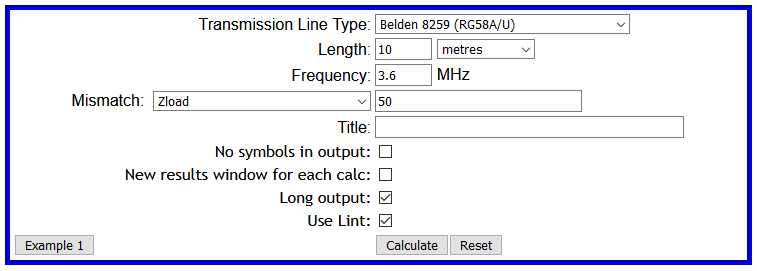
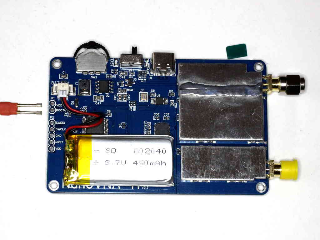
This article explores using a nanoVNA to measure line loss in a similar scenario. We will use 6m of Belden 8359 (RG58A/U) @ 3.6MHz.

The same technique could be used with a quality antenna analyser.

Expectation

A short digression, what is the specification Matched Line Loss (MLL) at 3.6MHz? Using TLLC we get 0.171dB, that is our expectation.

Return Loss of SC section

A common method proposed is to measure Return Loss (RL) of a section with load end RL=0dB and halve it. Many experts advise that the section should be terminated in a short circuit (S) because short circuits are more reliable than open circuits. So let’s get cracking.

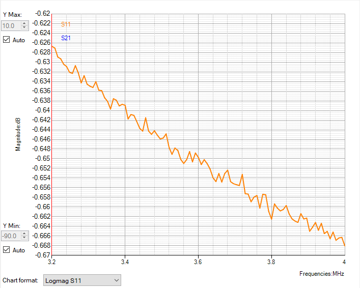
Above is measured |s11| using a nanoVNA with recent OSL calibration from 1-30MHz. |s11| @ 3.6MHz is by eye -0.651dB, RL=-|S11|, so RL/2=0.651/2=0.325dB. Continue reading Measuring coaxial cable loss by reflection with a VNA

Measuring coaxial cable loss by transmission measurement with a directional wattmeter

The article Measuring coaxial cable loss with a voltmeter discussed some pitfalls of that measurement method, starting with the influence of theoretical error in actual Zo at lower frequencies.

You might expect that using a directional wattmeter has exactly the same problems because as many online experts advise, at the end of the day they are just a voltmeter.

They are wrong, a Bird 43 might use a half wave detector driving a d’Arsonval meter and you might regard that to be a voltmeter, but the RF signal it measures is a combination of samples of forward and reflected waves wrt to its calibration impedance (usually 50+j0Ω) and we will see that makes a difference.

Where a directional wattmeter is calibrated for a purely real impedance (ie X=0), then the relationship \(P=P_{fwd}-P_{ref}\) holds true (On the concept of that P=Pfwd-Prev).

Lets take an example to explore the theoretical answer. We will use 10m of Belden 8359 (RG58A/U) @ 3.6MHz.

Lets model the scenario in TLLC. We will select the “Use Lint” switch for a better model of this specific cable at 3.6MHz and take the “Long” output.

Above is the input form. Continue reading Measuring coaxial cable loss by transmission measurement with a directional wattmeter

Measuring coaxial cable loss with a voltmeter

A question asked online about measuring terminated coax cable loss with an RF voltmeter and whether to condemn it based on comparison with specs raises an interesting case to discuss.

The subject raises some immediate concerns:

  • the accuracy of the termination;
  • the accuracy of the voltmeter;
  • the extent to which the voltmeter disturbs the thing being measured; and
  • assumptions about matched conditions.

Lets take an example to explore the theoretical answer. We will use 10m of Belden 8359 (RG58A/U) @ 3.6MHz.

Lets model the scenario in TLLC. We will select the “Use Lint” switch for a better model of this specific cable at 3.6MHz and take the “Long” output.

Above is the input form. Continue reading Measuring coaxial cable loss with a voltmeter

Simsmith bimetal line type

This article discusses various measurements and models of Wireman 551 windowed ladder line, including adapting Simsmith’s bimetal line type to bear on the problem.

Measurements

A starting point for characterising the matched line loss (MLL) of the very popular Wireman 551 (W551) windowed ladder line is the extrapolation of measurements by (Stewart 1999) to 1.8MHz. Since the measurements were made at and above 50MHz where the W551 has copper like performance, this is likely to underestimate actual MLL and such wide extrapolation introduces its own uncertainty. Nevertheless, the datapoint is MLL=0.00227dB/m.

Dan Maquire recently posted a chart summarising measurements of these lines.

For the purposes of this article, let’s tabulate the MLL at 1.8MHz in dB/m. Continue reading Simsmith bimetal line type

nanoVNA-H – recovery

This article applies to the original NanoVNA (v1) by edy555 / ttrftech, and the NanoVNA-H derivative.

I often see reports that a nanoVNA has been ‘bricked’. The term seems to have become part of the vernacular of would be pros. The term ‘bricked’ certainly applies to electronics that can no longer be programmed through ‘ordinary means’ and is to all intents and purposes as useful as brick, but in most cases, the nanoVNA is recoverable.

The STM32F072 chip  used on the original nanoVNA has some features that make the firmware update process simple and robust, and difficult to mess up.

The normal way of doing a firmware update is using the DFU protocol from a PC over the USB interface. To use this, the device has to be “put into DFU mode”, this means that the chip is reset and started executing the bootloader in permanent system memory.

The concept of DFU is that normal client programs used with the device can easily be extended to include the DFU function as just another menu function of the client software. NanoVNA-App does this, but in my experience most PC client programs do not.

So, you probably need to use a programming client, and for Windows a good choice is ST’s DfuSeDemo. You may need to convert the distributed file format using Dfu file manager from the same distribution, not all developers distribute a .dfu file.

There is a pin on the board, BOOT0, that must be held high during reset to enter the on-chip bootloader. Later firmware versions also provide a menu option to enter the bootloader, but if an attempted upgrade messes up the menu, you may need to use the BOOT0 pin bridged to the adjacent VDD pin while you power cycle the nanovna.

Some later hardware can be booted in DFU mode by pressing the jog button in while powering on.

Above is the rear view of the board, and a jumper using pogo pins to bridge BOOT0 to VDD. Continue reading nanoVNA-H – recovery

nanoVNA-H – rework of v3.3 PCB to v3.4?

nanoVNA-H v3.4 is out, and I don’t yet see significant problem reports.

When I compare the circuit with v3.3 (which I have), apart from new battery charger IC etc, the changes are in three areas:

  1. decoupling power to the mixers;
  2. increasing the drive to the mixers; and
  3. higher attenuation of input on the rx port. Continue reading nanoVNA-H – rework of v3.3 PCB to v3.4?

nanoVNA-H – v3.3 USB problems

At nanoVNA – measurement of two 920MHz LoRa antennas I mentioned my growing frustration with the USB interface on the nanovna, particularly the tendency to reset the nanoVNA with the slightest wiggle and the frustration in trying to use the resulting mess.

I have previously cleaned both plug and socket a couple of times, the last time was after some board modifications and flux residue was washed from the board keeping the USB socket dry, then the USB socket was flushed with clean solvent and blow dry.

The USB problems have become apparent only recently and rapidly got worse. Continue reading nanoVNA-H – v3.3 USB problems

nanoVNA – that demo board and its U.FL connectors

One of the many nanoVNA cloners makes an interesting little inexpensive demo board with a selection of components, filters etc to develop familiarity with the nanovna.

Above is a pic of the demo board and the supplied jumper cables. The demo board may not include information relevant to using the cables and connectors supplied. Continue reading nanoVNA – that demo board and its U.FL connectors