Directional wattmeters are used in lots of ham stations, yet we see evidence in social media posts that many people do not understand them and the measurement context.
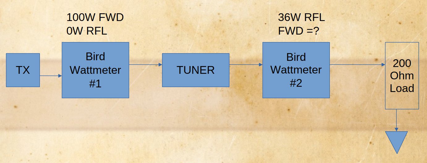
We have an RF source connected via a Bird 43 directional wattmeter with an appropriate 50Ω measurement element directly to a load resistance.
We measure the load voltage to be 100Vrms and the current to be 1Arms.
1. What is the power in the load?
100W
2. What does the directional wattmeter indicate for Pfwd?
112.5W
3. What does the directional wattmeter indicate for Prev?
12.5W
What is the implied VSWR?
2
4. Can the load power in this scenario be ‘measured’ using this instrument?
Yes, since the calibration impedance is a purely real value, measure Pfwd and Pref and calculate P=Pfwd-Prev.
Any surprises there?
Explanations to follow in the coming days.