The net abounds with articles on broadband transformers (ie untuned) for matching End Fed Half Wave (EFHW) antennas to 50Ω. One of the aspects that is common to most designs is that the turns of the primary winding are wound ‘bifilar’ with the start of the secondary winding, indeed the twist pitch is often very short and articles often go into detail on how to make this magic thing.
The magic is that it is supposed to give closer to ideal behaviour of the transformers by way of minimising flux leakage.
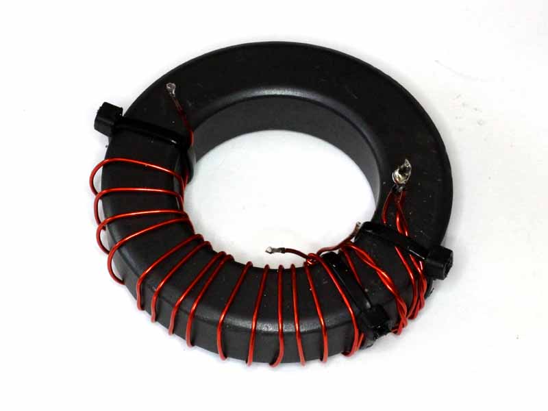 The transformer above is styled on the common design, and it consists of a 2t primary and 16t secondary where the primary is wound bifilar, and a third 2t winding wound over the primary end of the transformer between the other turns.
Inductance of the two 2t windings each was measured at around 700kHz (µ is close to µi), and the pair in opposition (L’). The inductances were 4.02, 4.01 and 0.02µH respectively. We can calculate mutual inductance M=(L1+L2-L’)/2=4.005µH. We can calculate flux coupling factor k=M/(L1*L2)^0.5=0.997.
There is negligible flux leakage between the 2t windings with µ in the region of 800.
A further test was made of inductance from the non-shared ends of each of the 2t windings to the 16t winding, and the inductances were both 184.4µH and the 16t winding was 237µH. If we follow the same procedure, we will find that the flux coupling factor between either 2t and 16t winding is 0.919, there is very little flux leakage, and the results between the two 2t windings are indistinguishable.
Note that the secondary winding has been spread out to occupy about half of the core, but common designs utilise all of the core, with or without the W1JR crossover, and using more of the core tends to increase flux leakage though the effect for this medium µ core will be small.
What happens with lower permeability?
Cores with lower permeability have higher flux leakage for the same winding geometry, and there are other changes.
What happens at higher frequencies?
The permeability of core material may vary with frequency, particularly ferrite.
Variations on published designs
Though these transformers are claimed to be broadband and have near ideal transformation, that is hardly the case. They are often frequency compensated with a capacitor in shunt with the primary, and the transformation is not simply Zin=Zload/n^2. That doesn’t make them unsuitable, it just makes the simplistic explanations inadequate.
The compensation capacitor depends on the core type, turns, frequency range and acceptable VSWR limit. I see designs where the core type was changed yet the compensation capacitor value was retained, resulting in an overcompensated transformer with worse behaviour than if the capacitor was omitted.
It is not unusual to see that a constructor has taken a design and substituted their own favourite ferrite mix in the belief that it is and independent variable of the design, and that their superficial analysis is meaningful.
Essentially, if the design was good in the first place (and that is often questionable), copy it exactly. If the design data does not give useful measurement data (including loss performance, thermals etc) to validate the design, perhaps keep looking.