For a lot of experiments, knowledge of the Equivalent Noise Bandwidth (ENB) of a receiver is necessary. The ENB is the bandwidth of an ideal rectangular filter with the same gain as some reference frequency, 1kHz is usually specified for SSB telephony receiver sensitivity measurement.
Though filters are often specified in terms of bandwidth at x dB down, that metric is of relatively little value, the x is often 6dB but not always, the filters depart significantly from ideal or even common response.
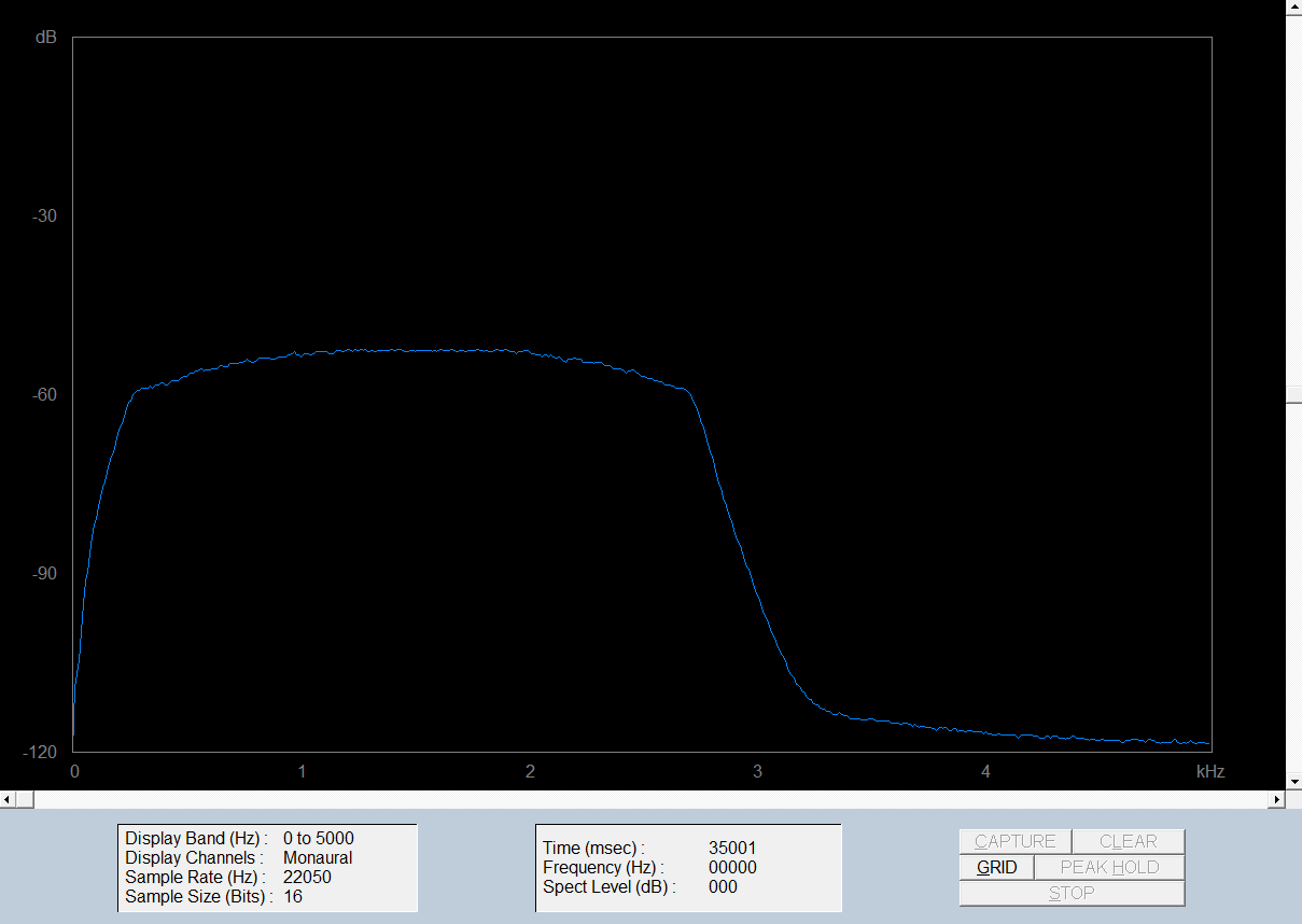
In brief, a white noise source is connected to the receiver input, Filter2 (nominal 2400Hz bandwidth soft response) selected and set to standard PBT, and the audio output captured on a PC based audio spectrum analyser, Spectrogram 16 in this case.
Spectrogram is set to integrate over 30s to average the variations due to the noise excitation. The resulting graph and text spectrum log are saved.
The method is explained in detail at Measure IF Bandwidth.

Above is the spectrum plots, as receivers go this is relatively flat, lacking the usual tapering off above 1kHz (a technique to cheat on sensitivity specs).
Continue reading Equivalent noise bandwidth – IC-7300 SSB Rx Filter2 (2400Hz soft)
Last update: 1st October, 2019, 7:58 PM