Standardised processing of instrument screen captures

I have several instruments and software packages that can create screen captures, and the capture files commonly need some mix of image processing including for example:

  • cropping;
  • scaling;
  • brightness, contrast, gamma adjustment;
  • transparency change;
  • format conversion; and
  • file copy / archive / cleanup.

Above is an example. Though WordPress presents a small image inline, if you click on it, there is a 640×480 image that was created from a QVGA (320×240) screen capture file scaled and gamma adjusted.
Continue reading Standardised processing of instrument screen captures

Review of Hantek DSO8102E hand held oscilloscope

This article is a brief review of some issues that were found with initial testing of a Hantek DSO8102E two channel 100MHz hand held oscilloscope.

The DSO8102E is a member of the DSO8000 series (DSO8060, DSO8070E, DSO8100E, DSO8150E, DSO8200E), and shares most specifications across the series.

The specifications are very impressive, and price at just under $1000 for a Chinese brand seemed reasonable (hand held oscilloscopes are expensive compared to bench oscilloscopes).

The test scenario was a practical application, observation of the data traffic to/from a DHT22 temperature and humidity sensor in the project ESP8266 IoT DHT22 temperature and humidity – evolution 2. Continue reading Review of Hantek DSO8102E hand held oscilloscope

Cheap and nasty 50Ω SMA terminations

Chinese sellers offer low cost 50Ω SMA terminations mostly without specs, but some sellers specify VSWR<1.2 to 3GHZ.

Above is the internals of one, it is a 51Ω 5% metal film resistor.

They often fail a DC test and tapping them gives erratic resistance readings up to hundreds of ohms, and of course they can be unreliable at RF.

They rely upon the resistor pigtail to make a spring contact with the inside of the barrel, and give that the pigtail is soft copper with little spring the contact is not very reliable. Continue reading Cheap and nasty 50Ω SMA terminations

A check load for antenna analysers with UHF series socket

Hams embrace the UHF series connectors like no one else, including for its use on test equipment where its performance is lacking.

This is the likely reason why it is so hard to find low VSWR 50Ω terminations with UHF series plug. It is rare to find something with VSWR quoted in specifications, and nigh on impossible to find one at a reasonably low price.

On the other hand, SMA terminations start at about $2 each (posted), and it is not too hard to find ones specified with VSWR<1.2 to several GHz.

Above is a low cost, low quality solution. It is a SMA termination selected from a bunch using a high accuracy DMM (selected, R is 49.86Ω) and a SMA(F)-UHF(M) adapter, total cost $7 (posted) (but you might be advised to buy 5 loads to select the best one). Despite the specification, they are probably only good to 100MHz, and can be unreliable. Continue reading A check load for antenna analysers with UHF series socket

EmonTx3 v3.4 ‘wired’ implementation

Introduction

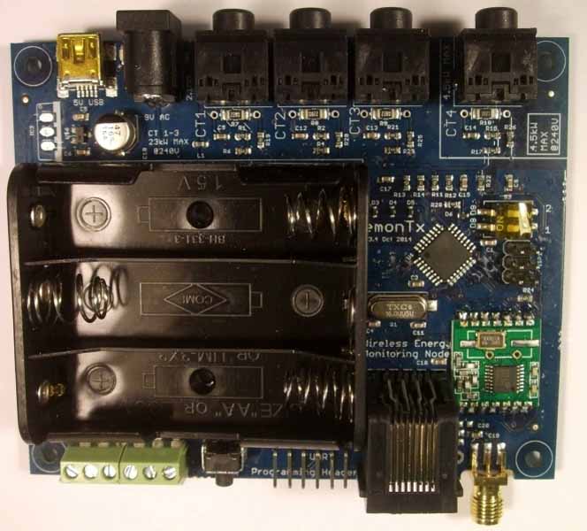
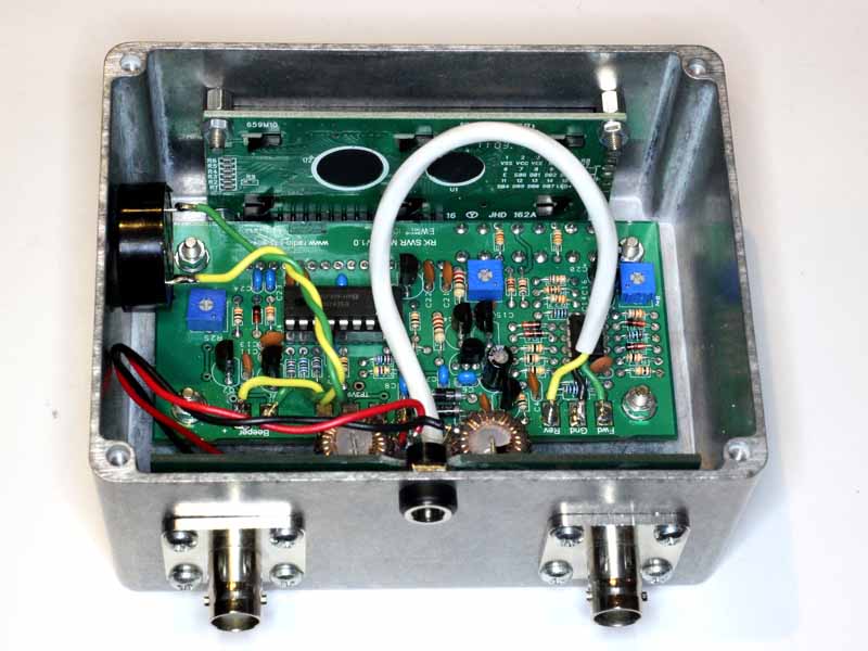
EmonTx3 is a measurement node for an energy measurement system. It has measurement inputs for 4 current transformers, AC voltage, 6 DS1820B temperature sensors and a meter pulse counting sensor.

The standard configuration uses a HopeRF RFM69CW radio transceiver to emonhub running on some host.

This article describes modifications to the system to use a wired serial connection to the emonhub host.

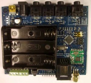
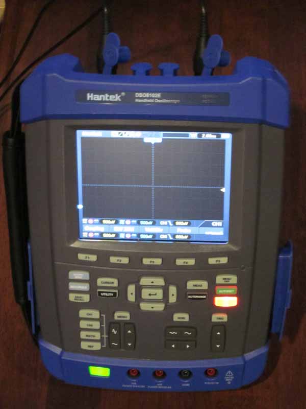
Above is the emonTx3 board.

The approach taken is a minimal change to existing firmware and software, no change to existing hardware, and inexpensive components to extend the connection.

Outline of the solution

The existing firmware writes a debug stream to the connector used for firmware upgrade. It is a different format to that used for the radio link, and there are good reasons for that, but it means writing an interface handler for emonhub to parse the debug stream.

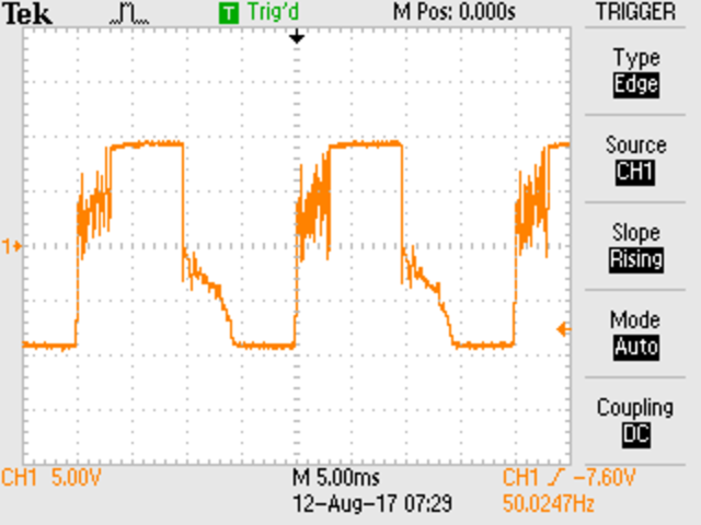
emonTx V3.4 Discrete Sampling V2.80
OpenEnergyMonitor.org

No EEPROM config
RFM69CW Node: 8 Freq: 433Mhz Group: 210

ct1:-51,ct2:0,ct3:0,ct4:0,vrms:23910,pulse:0,t0:223
ct1:-71,ct2:0,ct3:0,ct4:0,vrms:23924,pulse:0,t0:223
ct1:-6,ct2:0,ct3:0,ct4:0,vrms:23921,pulse:0,t0:223

The solution involves some hardware to interface the emonTx3 to the wire line, and a similar interface at the other end to the host running emonhub.

Hardware

Above is the debug stream from the modified firmware.
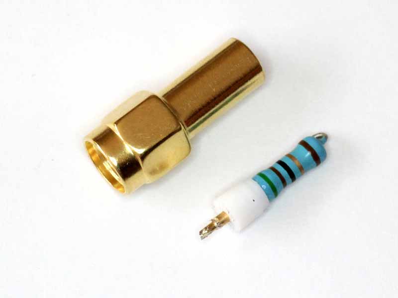
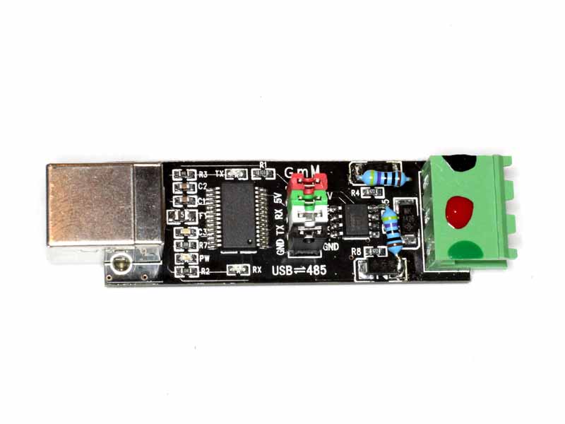
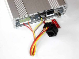
Above is an adapter (~$3) from the TTL levels of the UART port to RS485. The port is currently run at 115200bps, and that can be carried 800m with good noise immunity on good copper using RS485.

USB-485-10

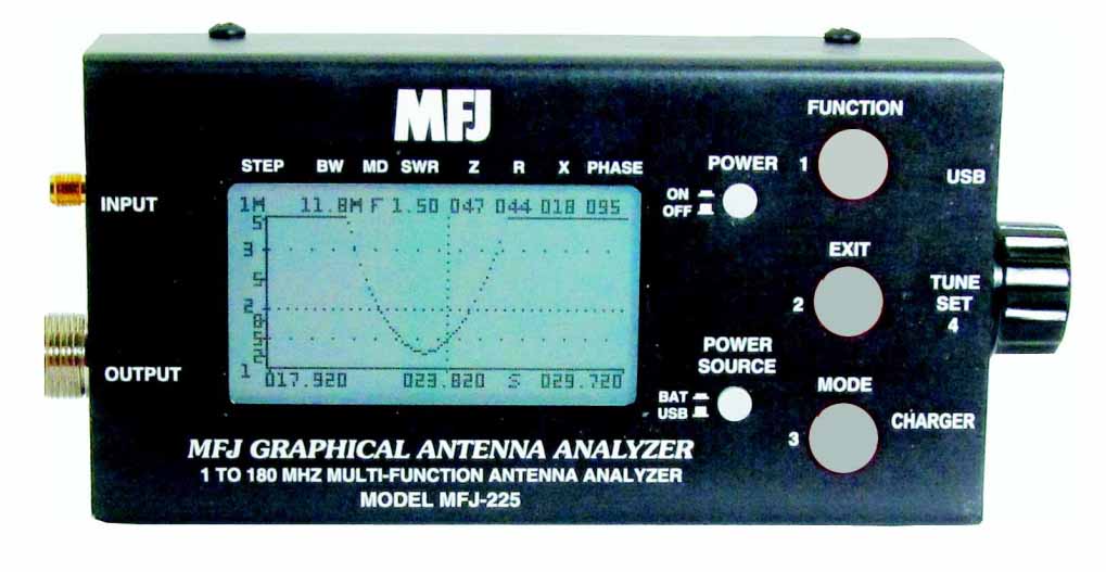
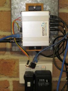
Above is the host end adapter.

Firmware changes

The firmware was changed to repurpose the output that may be used for switching power to the DS19B20 sensors, it is now used primarily as an RTS signal to the RS485 adapter to reduce current consumption when there is no traffic. In fact, the RTS signal has been asserted also at times when the DS18B20 sensors are read and it could also be used for its original purpose without conflict.

Host changes

Assigning a consistent name to the RS485 adapter

A problem with USB serial adapters is that they may acquire different device names depending on the order in which they are started.

This is solved in this solution by use of FTDI adapters which have a serial number that uniquely identifies the adapter, and setting udev rules to assign a consistent symbolic link to the device. It is this symbolic link that is used in emonhub.conf

The link is achieved by adding the file /etc/udev/rules.d/75-RS485.rules with the contents below (the contents must match the actual adapter).

#Assign fixed symlink to RS485 adapter for emonttx

SUBSYSTEM=="tty", ENV{ID_SERIAL}=="FTDI_FT232R_USB_UART_A9WRVDPD",SYMLINK+="ttyRS485-0"

The udevadm command will provide the information needed.

root@emonpi(rw):log# udevadm info -n /dev/ttyUSB0
P: /devices/platform/soc/20980000.usb/usb1/1-1/1-1.2/1-1.2:1.0/ttyUSB0/tty/ttyUSB0
N: ttyUSB0
S: serial/by-id/usb-FTDI_FT232R_USB_UART_A9WRVDPD-if00-port0
S: serial/by-path/platform-20980000.usb-usb-0:1.2:1.0-port0
S: ttyRS485-0
E: DEVLINKS=/dev/serial/by-id/usb-FTDI_FT232R_USB_UART_A9WRVDPD-if00-port0 /dev/serial/by-path/platform-20980000.usb-usb-0:1.2:1.0-port0 /dev/ttyRS485-0
E: DEVNAME=/dev/ttyUSB0
E: DEVPATH=/devices/platform/soc/20980000.usb/usb1/1-1/1-1.2/1-1.2:1.0/ttyUSB0/tty/ttyUSB0
E: ID_BUS=usb
E: ID_MODEL=FT232R_USB_UART
E: ID_MODEL_ENC=FT232R\x20USB\x20UART
E: ID_MODEL_FROM_DATABASE=FT232 USB-Serial (UART) IC
E: ID_MODEL_ID=6001
E: ID_PATH=platform-20980000.usb-usb-0:1.2:1.0
E: ID_PATH_TAG=platform-20980000_usb-usb-0_1_2_1_0
E: ID_REVISION=0600
E: ID_SERIAL=FTDI_FT232R_USB_UART_A9WRVDPD
E: ID_SERIAL_SHORT=A9WRVDPD
E: ID_TYPE=generic
E: ID_USB_DRIVER=ftdi_sio
E: ID_USB_INTERFACES=:ffffff:
E: ID_USB_INTERFACE_NUM=00
E: ID_VENDOR=FTDI
E: ID_VENDOR_ENC=FTDI
E: ID_VENDOR_FROM_DATABASE=Future Technology Devices International, Ltd
E: ID_VENDOR_ID=0403
E: MAJOR=188
E: MINOR=0
E: SUBSYSTEM=tty
E: TAGS=:systemd:
E: USEC_INITIALIZED=8089809829

Interfacer module to parse the debug stream

An additional interfacer module was written to parse the debug stream, and it was hooked to the main module.

The interfacer is configured in emonhub and port layout copied in from source.

(the contents must match the actual adapter).

#Assign fixed symlink to RS485 adapter for emonttx

SUBSYSTEM=="tty", ENV{DEVLINKS}=="*usb-FTDI_FT232R_USB_UART_A9WRVDPD*",SYMLINK+="ttyRS485-0"

Code source

Code source is available the original git emonhub repo, and in the following git repository forked from the official repo:

Test

The wired configuration is under test with emonhub installed on a Ubuntu server, and about 40m of cat5e cabling from emonTx3 to host. No issues have arisen.

References / links

EmonTx_V3.4

Check / calibrate frequency accuracy of IC-7300

The IC-7300 is a transceiver where all heterodyning oscillators are derived from a single master oscillator.

This type of radio makes for very easy checking and calibration of frequency accuracy.

The video below demonstrates the technique.

The video used a local GPS disciplined source at 50.1MHz. The frequency was chosen to provide the greater resolution in setting the oscillator, though setting it to within 1 part in 50,000,000 or 0.02ppm is better than the stability of the oscillator (specification is 0.5ppm or 5Hz at 10MHz).

Any accurate known reference can be used, it could be WWV or the like, or even a MW broadcast station, though an accurate signal at 10MHz or higher is better.

The technique can be applied to the much older IC-7000, and many transceivers released since then, of various brands. The important thing is that ALL oscillators are derived from a single master oscillator.


Reflected power alarm for the MFJ-993B

This article describes an add-on to a MFJ-993B auto ATU to provide an audible alarm when reflected power exceeds a set threshold. A deficiency of the original design IMHO.

The solution uses the generic heating / cooling controller (hcctl) configured for its alarm function only, including a function to silence the alarm.

screenshot-03_12_16-18_34_50Above is the directional coupler part of the MFJ-993B. The REF test point is designed to present voltages within the range 0-5V when used within the stated power ratings. Continue reading Reflected power alarm for the MFJ-993B

Radio-Kits SWR meter – build and review

This article describes my build of a Radio-Kits SWR meter (v1.1) and post implementation review.

Advertised features:

  • HF coverage – 1.8-30MHz
  • Displays VSWR, forward power, reverse power and supply voltage
  • Peak reading power meter
  • Bar graph or numerical format
  • Reverse power alarm with adjustable threshold
  • Auto turn on in presence of RF – sensitivity about 1 watt
  • Optional turn off after preset time – 10-240 seconds
  • Backlit LCD display with variable brightness
  • Reverse polarity protection

I purchased the kit some years ago, and on receiving it and reviewing the circuit I formed the view that it was likely to have unacceptable Insertion VSWR on 1.8Mhz, and probably 3.5MHz bands… so I lost interest in assembling the kit. However, I have belatedly constructed the kit, calibrated and tested it.

Implementation

The kit is supplied as a PCB and parts, no casework is supplied.

The board was difficult to solder, the strain relieved ground plane connections of components have very little donut to contact for heat transfer and are much harder to solder than the other pads. The strain relief is a dubious feature that makes soldering difficult.

rkswr01

Above, the kit assembled in a die-cast aluminium box. An opening for the LCD was milled into the box, and holes drilled for the rest of the fit up. The kit does not lend itself to this boxing as the buttons out the top and display out the front are a problem to fit up. A poor mechanical design.

rkswr02

Above is the interior of the box showing the LCD display and the external BNC connectors fitted (substituted for the ubiquitous UHF connectors supplied with the kit). Continue reading Radio-Kits SWR meter – build and review