DL4YHF 50MHz counter on a Chinese TB-244746 PCB

DL4YHF published a frequency counter design based on the PIC16F628.

The design has been modified by many, copied by even more, and usually without attribution.

This article documents one of these copies (TB-244756 printed under the chip footprint), a $6 kit off eBay which comes with no documentation, though the screen mask is enough to correctly place components.

It turns out to be DL4YHF’s “DISPLAY_VARIANT 2”, the variation is that it uses a common cathode display.

Above the built kit with the 7550 voltage regulator replaced with a 78L05. Continue reading DL4YHF 50MHz counter on a Chinese TB-244746 PCB

Review: magnetic stirrer with heating plate and digital display XB 85-2

I purchased a laboratory style stirrer / hotplate with PID temperature controller for some experiments.

Above, the 85-2 product from Chinese maker XB.

It certainly looks the part and for under $100 looked impressive value… but was it?

Is it safe?

First thing with ANY Chinese appliance is to test the electrical safety. Prior to a full PAT test, I plugged it in on an insulated work space and waved a non-contact voltage detector over the case. Beeeep! The case is hot. Earth continuity (earth pint to case) is zero, there is no connection. This came with an AU plug… so lets look inside at how they wired it up.

The green yellow earth wire is floating look, the end has been tinned so it was or was intended to be soldered to something. The end of one of the screws holding four rubber feet on is more silver coloured than the others, so it appears to have been tacked on to that. Three issues: the screw tension is cushioned by the rubber foot and pressure to case is low so it would not be a reliable low resistance connection; soldered ground connections can melt off in a fault and are unacceptable practice; and the even this had become disconnected and would not have passed a basic electrical test. Chinese Quality!

So with the cover off, it is apparent just a few months after this May 2017 dated build has been put together with rusty steel. Continue reading Review: magnetic stirrer with heating plate and digital display XB 85-2

Demonstration of the GR1606B for antenna Z measurement and calcs

This article demonstrates use of a GR1606B RF impedance bridge for measurement of the feed point impedance of a MHz loaded mobile whip. The antenna is roof mounted on a vehicle and measurements are made looking into 4m of RG58C/U, then transformed to feed point impedance using three tools:

Key metrics are:

  • F=7.05MHz
  • R=35Ω
  • ReactanceDial offset=200
  • ReactanceDial=442
  • X=(442-299)/7.05=34.33Ω
  • Z=35+j34.33Ω;
  • Feed line is 4m of Belden 8262 (RG58C/U).

Continue reading Demonstration of the GR1606B for antenna Z measurement and calcs

Inside the YHDC SCT013 current transformer

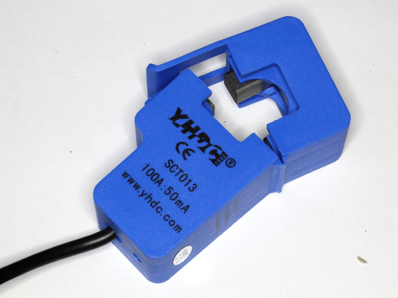
The YHDC SCT013 series is very popular for use in energy monitor projects.

Disassembly

Warning, the core is VERY hard, but VERY brittle, don’t hit it with anything hard, don’t grip in with pliers, don’t drop it on a hard surface.

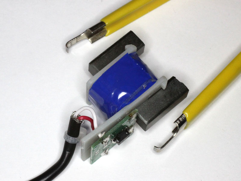
The coil and half core are held in the lower housing by two obvious catches which click over the bobbin. Removal means pulling the assembly upwards gently whilst releasing the catches and feeding cable into the housing. One of the catches will probably catch on the slot in the bobbin, be prepared to release it.


An ideal tool for the purpose is an ordinary $2 DIP chip puller which can be used to get purchase on the two ears on the bobbin that can be seen in this pic. Push a little cable into the housing, pull upwards while releasing the catches, then feed more cable and the assembly is pulled upwards from the housing.

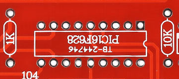
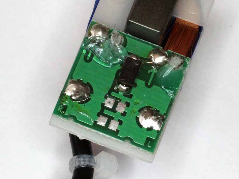
Above is the PCB detail. This one has a TVS (the black component) and no burden resistors. There is a place for two parallel 0806 burden resistors on the board.

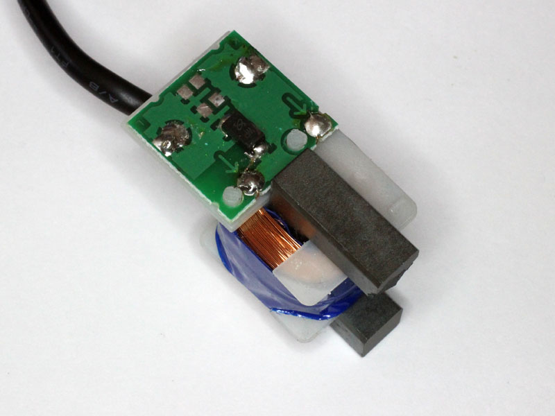
The PCB floats on two plastic pin extensions of the bobbin. You may obtain benefit in securing it with two very small fillets of hot melt adhesive as above, small enough so as to not interfere with the guide rails in the enclosure.

Burden resistors

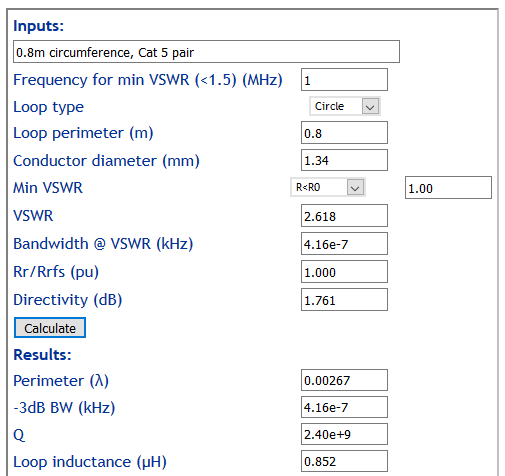
So if you wanted to add a burden resistor for 0.333V out at 50mA secondary current, R=0.3333/0.05=6.6667. You could do this with 1% resistors in the E12 value series, 12Ω and 15Ω will give the desired resistance. Likewise for 1V out, 22Ω and 220Ω in parallel will give the desired value of 20Ω.

If you wish to remove existing burden resistors, they can be removed with specialised tooling but small SMD resistors will usually melt the other side solder moments after melting the first side. Position a toothpick with one had to push the resistor sideways, with the other and use the soldering iron to eat one side to melt, move the soldering iron to the other side and push the resistor sideways with the toothpick as soon as both sides melt.

Protection

A CT that has no load could develop extreme and damaging voltage within the secondary winding in the presence of primary current. If the CT assembly does not have an integral burden resistor, it is wise to install a TVS or pair of inverse series 9V Zener diodes to prevent excessive voltage lest the external load be disconnected.


BG7TBL noise source

This is a review of the BG7TBL noise source available on eBay for about $20 incl post. I have seen this recommended in various online forums and thought it worthy of review.

A quick mention of Excess Noise Ratio (ENR), it is a commonly used measure of the characteristic of noise sources. A noise source for testing low noise RF amplifiers needs to be less than 10dB, 5dB is common; for other receiver testing around 15dB is common, and for massive output for filter alignment etc the noise needs to be well above a spectrum analyser noise floor so an ENR of 50dB might be appropriate (but such high noise output makes it useless for LNA noise figure measurement),

Above is the device. The layout is pretty simple, it is a Zener noise source at the left followed by three MMIC amplifier stages. The circuitry at mid left is a DC-DC converter to supply 25V to the Zener.

There are a host of aspects so far that are concerning:

  • there is no need to operate the Zener at such high voltage;
  • lack of regulation of MMIC power supply;
  • the noise output of the Zener source should be quite high; and
  • three stages of MMIC will give rise to huge output, notwithstanding the on-board attenuators at Zener output and final MMIC output.

Continue reading BG7TBL noise source

Inductance of a loop of CAT5 pair

An online expert recently reported:

I tried to make an antenna loop for longwave with cat 5 and after it did no good I realized the twisted wires canceled each other out.

Or did they really cancel?

Parallel connection

I constructed a loop of one Cat 5 pair and measured its inductance when both wires are bonded at the ends.

The conductors are 0.5mm diameter and spaced 0.9mm. To estimate the inductance we use the geometric mean radius (GMR) as the equivalent radius of the pair. GMR=(0.5*0.9)^0.5=0.67, diameter=1.34mm. So let’s calculate the inductance of a single turn circular loop of 0.8m perimeter and round conductor of 1.34mm diameter.

The estimate above is 850nH.

Above is the measurement, the screen is not readable, but it is 852nH, very close to the estimated 850nH. Continue reading Inductance of a loop of CAT5 pair

Calibrating the Elecraft N-GEN

The Elecraft N-GEN is a low cost noise source which is quite suited to many applications, more so if the Excess Noise Ratio (ENR) is known.

ENR is a commonly used property to describe the noise power density of a source, it is calculated as ENR=10*log(Tne-T0)/T0 dB where Tne is the quivalent noise temperature and T0 is 290K.

This article describes a calibration procedure. Note that the calibration is specific to the device and cannot be applied to another N-GEN.

Above is a screenshot of the Spectrum Analyser scan. A text file of the frequency,power pairs is saved for input to a spreadsheet to calculate ENR vs frequency. Continue reading Calibrating the Elecraft N-GEN

Equivalent noise bandwidth – IC-7300 SSB Rx Filter2 (2400Hz soft)

For a lot of experiments, knowledge of the Equivalent Noise Bandwidth (ENB) of a receiver is necessary. The ENB is the bandwidth of an ideal rectangular filter with the same gain as some reference frequency, 1kHz is usually specified for SSB telephony receiver sensitivity measurement.

Though filters are often specified in terms of bandwidth at x dB down, that metric is of relatively little value, the x is often 6dB but not always, the filters depart significantly from ideal or even common response.

In brief, a white noise source is connected to the receiver input, Filter2 (nominal 2400Hz bandwidth soft response) selected and set to standard PBT, and the audio output captured on a PC based audio spectrum analyser, Spectrogram 16 in this case.

Spectrogram is set to integrate over 30s to average the variations due to the noise excitation. The resulting graph and text spectrum log are saved.

The method is explained in detail at Measure IF Bandwidth.

Above is the spectrum plots, as receivers go this is relatively flat, lacking the usual tapering off above 1kHz (a technique to cheat on sensitivity specs).
Continue reading Equivalent noise bandwidth – IC-7300 SSB Rx Filter2 (2400Hz soft)

GPS antenna plot

I bought an inexpensive GPS antenna on eBay, the requirement was for one that operated from 3-5V to suit both of my GPSDOs. The antenna is mounted in an electrical junction box on conduit above the roof for reliable coverage.

The question was whether the active antenna with 5m of RG174 coax and SMA male connector at A$6 posted was any good.

To map its behaviour, it was attached to a Trimble Thunderbolt GPSDO and Lady Heather used to plot rx signal level over about 30h.

Above is the plot. The pattern is not quite symmetric as there are obstructions in play, in fact some of the dips in performance are explained by specific trees and the roof profile. There is a gap to the south at low elevations, GPS satellites don’t fly there (MEO inclined 55° from the equator) .

Overall, it reaches similar strength at the zenith as other antennas tried.

Overall evaluation, it seems to work ok though the coax is a bit rough.

Inductance of sensorless brushless DC motors

A reader of A Demagnetisation Risk Index for a sensorless brushless DC drive asked whether the inductance of a sensorless brushless DC motor could be measured with one of the inexpensive LC meters available on eBay.

Motor inductance line-line typically ranges from several µH up towards 100µH. Importantly, the fundamental frequency of flux change in the laminated iron core under normal operation is typically less than 2kHz.

Validation of the LC200A

To verify the instrument, a test inductor was made with 3t on a FT-240-43 ferrite core.

Above is an estimate of the expected inductance of the test inductor, 9.65µH. Keep in mind that the tolerance of ferrite is quite wide, 20% variation is not unusual. The test inductor measured 9.1µH at 10kHz on a classic RLC meter.

Above, the LC200A measuring an inductor comprising 3t on a FT240-43 ferrite core, measurement frequency was 670kHz. The measured inductance is 8.98µH, 7% lower than the estimate but well within tolerance of the ferrite core, and less than 2% below the value measure with a classic RLC meter. Continue reading Inductance of sensorless brushless DC motors