I often receive emails from folk trying to validate continued performance of an installed antenna system using their analyser.
With foresight they have swept the antenna system from the tx end and saved the data to serve as a baseline.
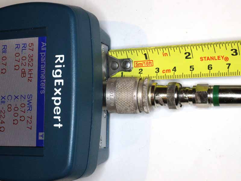
The following are example sweeps from one of my own antennas, a Diamond X50N with 10m of LDF4-50A feed line.
Now I have plotted Return Loss rather than VSWR for several reasons:
- Return Loss is more sensitive to the problems that we might want to identify;
- Rigexpert in this case decided that the Antscope user could not be interested in plotting VSWR>5 (Return Loss<3.5dB).
Now a hazard in working with Return Loss is that many authors of articles and software don’t use the industry standard meaning.
Return Loss
Lets just remind ourselves of the meaning of the term Return Loss. (IEEE 1988) defines Return Loss as:
(1) (data transmission) (A) At a discontinuity in a transmission system the difference between the power incident upon the discontinuity. (B) The ratio in decibels of the power incident upon the discontinuity to the power reflected from the discontinuity. Note: This ratio is also the square of the reciprocal to the magnitude of the reflection coefficient. (C) More broadly, the return loss is a measure of the dissimilarity between two impedances, being equal to the number of decibels that corresponds to the scalar value of the reciprocal of the reflection coefficient, and hence being expressed by the following formula:
20*log10|(Z1+Z2)/(Z1-Z2)| decibel
where Z1 and Z2 = the two impedances.
(2) (or gain) (waveguide). The ratio of incident to reflected power at a reference plane of a network.
Return Loss expressed in dB will ALWAYS be a positive number in passive networks.
The relationship between ReturnLoss in dB and VSWR is given by the equations:
- ReturnLoss=-20*log((VSWR-1)/(VSWR+1))
- VSWR=(1+10^(-ReturnLoss/20))/(1-10^(-ReturnLoss/20))
Diamond X50N on 2m
So now that we are on the same page about Return Loss, lets look at my 2m plot.
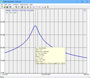
The X50N does not have VSWR or Return Loss specs, but we might expect that at the antenna itself, VSWR<1.5 which implies Return Loss>25dB. Measuring into feed line, you can add twice the matched line loss to the Return Loss target (see why Return Loss is a better measure).
Continue reading Baselining an antenna system with an analyser
Last update: 29th January, 2018, 11:49 AM