nanoVNA – that demo board and its U.FL connectors

One of the many nanoVNA cloners makes an interesting little inexpensive demo board with a selection of components, filters etc to develop familiarity with the nanovna.

Above is a pic of the demo board and the supplied jumper cables. The demo board may not include information relevant to using the cables and connectors supplied. Continue reading nanoVNA – that demo board and its U.FL connectors

nanoVNA user post provides an interesting example for study #1

At https://groups.io/g/nanovna-users/message/9185 a user posted a measurement made with his nanoVNA of a length of coax with termination.

Above is his initial reported measurement of an approximate 350′ length of coax with a known good dummy load on the opposite end. 350′ is 106.7m. Whilst this chart is less value than a Smith chart rendering, understanding the nature of things allows us to infer the Smith chart. Continue reading nanoVNA user post provides an interesting example for study #1

Normalised RMS voltage of a full wave phase controlled power waveform

The recent article Soldering iron – temperature control failure gave a plot of V’rms vs conduction angle for a simple full wave phase controlled AC waveform, and I have been asked to explain the derivation.

The phase controlled switch turns on at some delayed time from the zero crossing of the AC waveform, and conducts until the next zero crossing.

With the simplest circuits, there is a practical limit to the achievable stable range of conduction angle, and a minimum of about 50° to a maximum of about 160° is typical.

The RMS voltage is the square root of the mean of the square of the instantaneous voltage. We can write an expression for the normalised RMS voltage as a function of conduction angle θ. Continue reading Normalised RMS voltage of a full wave phase controlled power waveform

nanoVNA-H – measure 144MHz Yagi gain – planning / feasibility

This article documents a feasibility study of using the modified nanoVNA-H to measure the gain of a 4 element 144MHz Yagi, the DUT.

The intended configuration is the DUT will be connected to the tx port (Port 1 or CH0 in nanoVNA speak), and a known ‘sense’ antenna connected to its rx port (Port 2 or CH1 in nanoVNA speak).

nanoVNA |s21| noise floor

To make useful measurements of the received signal, the rx signal level must be a reasonable amount higher than the noise floor, 10dB should be sufficient.

Above is a plot of the |s21| noise floor around 146MHz. Continue reading nanoVNA-H – measure 144MHz Yagi gain – planning / feasibility

Antennas – disturbing the thing being measured – open wire lines #6

The article Antennas – disturbing the thing being measured – open wire lines #5 demonstrated an inconsistency between the notion of a balun Common Mode Rejection Ratio CMRR property and a complete NEC model for predicting common mode current behavior.

In that case, two scenarios were modelled with only a change in the feed line length, yet they showed quite different currents near the same balun.

A common metric bandied around is the Common Mode Rejection Ratio (CMRR) and the definition is a bit rubbery, but it tends to come down to the ratio of the magnitude of common mode current to the magnitude of differential current in a test scenario (usually a lab workbench… with intention that the metric is then applicable more generally). (Anaren 2005) gives a popular explanation.

It is worth noting that the conventional meaning of CMRR in relation to op amps is that it is the ratio of differential gain to common mode gain and large +ve dB values are goodness, and it makes sense. Common use in terms of baluns is the opposite, Anaren gives the expression CMRR=S1c/S1d which will give large -ve dB values as goodness, and which seems inconsistent with the descriptive name where a large ratio (more +ve dB value) would be goodness. The balun ‘crowd’s’ use of a -ve rejection ratio seems a bit tautological, as if they haven’t really thought this through, it is a bit like the hammy thing of talking about the attenuation of a length of coax as -xdB.

I don’t think CMRR is a useful property of baluns per se, certainly not as a component of practical antenna systems, so I have written this article to report common mode ratio (CMR) (being the ratio of common mode to differential mode current at the point of interest). CMR is not a property of the balun, it expresses the relationship between the magnitudes of the components of current at a point of interest.

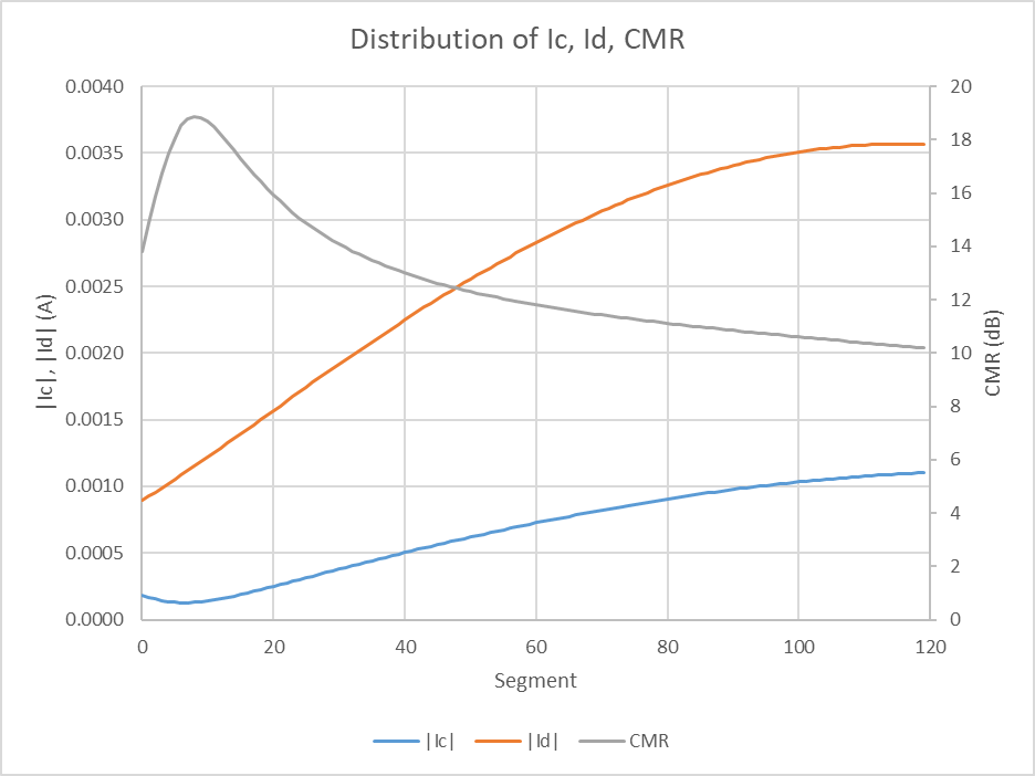
Keeping in mind that the differential current and common mode current distributions are usually both standing waves in the general case (usually with different phase wavelength and therefore relative phase), another dimension of the antenna problem is to look at the current distribution on the feedline of the NEC model scenario used for this series of articles. The model used here is the 20m feed line height and current balun with Zcm=1130+j1657Ω.

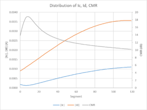
Above is a plot of |Ic|, |Id| and CMR in the NEC-4.2 model scenario. Segments are numbered from the lower end to upper end of the 20m long feed line. Continue reading Antennas – disturbing the thing being measured – open wire lines #6

Antennas – disturbing the thing being measured – open wire lines #5

The articles Antennas – disturbing the thing being measured – open wire lines #3 Antennas – disturbing the thing being measured – open wire lines #4 demonstrated an inconsistency between a partial linear circuit model and a complete NEC model for predicting common mode current behaviour.

One of the oft proposed solutions to characterising a balun is to find the Common Mode Rejection Ratio (a term carried over from other applications, eg voltage driven operational amplifiers). (Anaren 2005) explains a method of finding balun CMRR.  (Skelton 2010) goes so far as to say

The Common Mode Rejection Ratio (CMRR) of a balun is defined in professional literature as the ratio of wanted to un-wanted transmitted power. As rejection of common-mode transmission is the primary purpose of a balun, it follows that CMRR should be the key figure of merit.

Let us take the model scenario used in Antennas – disturbing the thing being measured – open wire lines #4 and lower the height of the dipole 10 10m, and compare the model ratio of Ic/Id.

Again, we will use Python to do the complex maths for the without and with scenarios at 20m height, and without and with at 10m height. Continue reading Antennas – disturbing the thing being measured – open wire lines #5

Antennas – disturbing the thing being measured – open wire lines #4

The article Antennas – disturbing the thing being measured – open wire lines #2 did a simple analysis of current flows in the model scenario using ideal voltage balun drive with a current balun.

It was mentioned that solution of the lumped values network is only a first approximation and not as good as the NEC solution which properly models the coupled conductors, and their mutual effect on the distribution of currents in the system.

This article reports the NEC current solution decomposed into differential mode and common mode components.

Ideal voltage balun drive

Above is a zoomed in view of the feed point with a balanced pair of voltage sources feeding the line against the ground electrode. Continue reading Antennas – disturbing the thing being measured – open wire lines #4

nanoVNA-H – measure 40m low pass filter for WSPRlite flex

This article demonstrates the use of a nanoVNA-H to measure the response of a low pass filter designed to pass 7MHz frequencies but attenuate harmonics. The inductors and capacitors make a seven element Chebyshev filter as designed by G3CWI for use in a 50Ω system.

Implementation

Above, the filter is assembled on a piece of matrix board with two BNC connectors. The inductors are fixed with hot melt adhesive, and the whole thing served over with heatshrink tube. It is not waterproof. Continue reading nanoVNA-H – measure 40m low pass filter for WSPRlite flex

Antennas – disturbing the thing being measured – open wire lines #3

The article Antennas – disturbing the thing being measured – open wire lines #2 did a simple analysis of current flows in the model scenario using ideal voltage balun drive.

That begs the question, what difference would a good current balun make?

We can get a good approximation of what happens by inserting the current balun’s Zcm in series with Z3. Let’s take Zcm to be 1130+j1657Ω (11t on a FT240-43). Continue reading Antennas – disturbing the thing being measured – open wire lines #3