Intending to enhance my generic heating / cooling controller to read SPI temperature sensors, I purchased an Adafruit MAX31855 module on eBay from a local supplier for about A$26 posted.
The module you might have guessed uses a MAX31855, a Cold-Junction Compensated Thermocouple-to-Digital Converter for K type thermocouple with an SPI interface. The Adafruit module includes a regulator and level translators to use it in a 5V system.
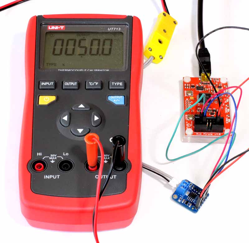
This article describes a simple checkout using a BusPirate V4. Conveniently, the MAX31855 module can be powered from the BusPirate. The thermocouple input is provided by a thermocouple calibrator.
After a short wait to allow both devices to stabilise at ambient temperature, a test was run. The BusPirate session is as follows.
HiZ>m
1. HiZ
2. 1-WIRE
3. UART
4. I2C
5. SPI
6. 2WIRE
7. 3WIRE
8. KEYB
9. LCD
10. PIC
11. DIO
x. exit(without change)

(1)>5
Set speed:
 1. 30KHz
 2. 125KHz
 3. 250KHz
 4. 1MHz

(1)>
Clock polarity:
 1. Idle low *default
 2. Idle high

(1)>
Output clock edge:
 1. Idle to active
 2. Active to idle *default

(2)>
Input sample phase:
 1. Middle *default
 2. End

(1)>
CS:
 1. CS
 2. /CS *default

(2)>
Select output type:
 1. Open drain (H=Hi-Z, L=GND)
 2. Normal (H=3.3V, L=GND)

(1)>2
Ready
SPI>W
POWER SUPPLIES ON
SPI>[r:4]
/CS ENABLED
READ: 0x00 0x18 0x15 0x70
/CS DISABLED
SPI>[r:4]
/CS ENABLED
READ: 0x03 0x24 0x15 0x90
/CS DISABLED
The first read was for 0° input, the second for 50° input.
0x157 gives the compensation temperature to be 21.4375° which is acceptable. 0x18 right shifted two bits gives 0xC or 3° (for 0°) and 0x324 right shifted two bits gives 0xC9 or 50.15° (for 50°). This is quite acceptable for a quick test, and demonstrates that the protocol variant and data structure is understood.