Surecom SW-102 VSWR meter review

I recently purchased a Surecom SW-102 VSWR meter. It looked a little like a supercharged RedDot copy.

sw102-02

Above the Surecom SW-102 VSWR meter with backlight and photographed under normal interior lighting. The display lacks contrast, and overall is difficult to read due to size of text, fonts used, and lack of contrast. (The pic is taken with a screen protector installed, but the evaluation is based on the bare meter with original protective film removed as it degraded readability.) Continue reading Surecom SW-102 VSWR meter review

Exploiting your antenna analyser #26

Find coax cable velocity factor using a very basic analyser

A common task is to measure the velocity factor of a sample of coaxial transmission line using an instrument that lacks facility to backout cable sections or measure SOL calibration (as discussed in other articles in this series). The older models and newer budget models often fall into this category.

The manuals for such instruments often explain how to measure coaxial cable velocity factor, and the method assumes there is zero offset at the measurement terminals (whether they be the built-in terminals or some fixture / adapters). In fact even the connectors are a source of error, especially UHF series connectors.

It is the failure to read exactly Z=0+j0Ω with a S/C applied to the measurement terminals that adversely impacts efforts to measure resonant frequency of a test line section.

The method described here approximately nulls out offsets in the instrument, measurement fixture, and even in the connectors used and for that reason may sometimes be of use with more sophisticated analysers.
Continue reading Exploiting your antenna analyser #26

PD7MAA’s BN43-202 matching transformer for an EFHW – full measurement set

I have written some recent articles about or relevant to PD7MAA’s BN43-202 EFHW matching transformer. At about the same time a discussion started on and through that discussion, one ‘online extra expert’ stated that my analysis was bogus (dictionary meaning: not genuine, faked, a misrepresentation).

This article presents detail that was not included in the earlier articles as it distracts from the issue for most readers. Continue reading PD7MAA’s BN43-202 matching transformer for an EFHW – full measurement set

Common failings of EFHW matching transformers

I have written many reviews of published EFHW matching transformers, and in most cases the reviews have reported estimated or measured losses that are appalling and not disclosed by the ‘designers’.

Why is it so?

I am asked, why is it so?

Up front, I do not know the answer definitively, but let me offer some thoughts based on the designer’s own articles and discussions by ‘online experts’.

Apparent reasons include:

  1. lack of understanding of ferrite and powdered iron core material behaviour;
  2. lack of understanding of coupled coils, and mutual inductance;
  3. use of inductor design tools that are inadequate at radio frequencies;
  4. lack of competency in basic linear circuit theory analysis for AC circuits;
  5. failure to make meaningful measurements of the built article;
  6. focus on input VSWR as a single metric indicating goodness;
  7. reliance on QSOs for evidence of performance;
  8. an attitude that antenna system radiation efficiency doesn’t matter, particularly for QRP (if the term antenna system radiation efficiency is even understood as a quantitative metric).

Continue reading Common failings of EFHW matching transformers

PD7MAA’s BN43-202 matching transformer for an EFHW – measurement of a prototype

At PD7MAA’s BN43-202 matching transformer for an EFHW I gave an estimate of the core loss in PD7MAA’s transformer.

This article reports measurement of a prototype built to his design.


Above is PD7MAA’s graphic for his transformer. It is a little confusing as an 11t wind will start and finish with ends as the blue wind, so the red winding must have and odd number of half turns which suggests the windings are actually 1t and 5.5t (pity he did not show a picture of the real transformer).

PD7MAA gives some measurements for his transformer with a 3300Ω load, but he does not give loss measurements. This experiment is to replicate his configuration, measure the loss and compare it to the estimate given at PD7MAA’s BN43-202 matching transformer for an EFHW.

The prototype uses 1t primary and 5.5t secondary. The secondary load is a 3300Ω resistor in series with the VNA 50Ω input port.

Above is a screen shot of a sweep from 6 to 8MHz. The key data is that shown for the marker at 7.1MHz. Continue reading PD7MAA’s BN43-202 matching transformer for an EFHW – measurement of a prototype

PD7MAA’s BN43-202 matching transformer for an EFHW

End Fed Half Waves have certainly captured the minds of QRP aficionados, and there is a steady stream of ‘designs’ appearing on the ‘net.

A recent article by PD7MAA describes such a transformer using a BN43-202 balun core for up to 20W PEP from 7-29MHz.

Above is PD7MAA’s graphic for his transformer. It is a little confusing as an 11t wind will start and finish with ends as the blue wind, so the red winding must have and odd number of half turns which suggests the windings are actually 1t and 5.5t (pity he did not show a picture of the real transformer). Let’s proceed under that assumption. Continue reading PD7MAA’s BN43-202 matching transformer for an EFHW

Exploiting your antenna analyser – contents

A convenient list of ‘Exploiting your antenna analyser’ and short subject sub-titles, a table of contents for the series as it grows.

Exploiting your antenna analyser #30 Quality of termination used for calibration

Exploiting your antenna analyser #29 Resolving the sign of reactance – a method – Smith chart detail

Exploiting your antenna analyser #28 Resolving the sign of reactance – a method

Exploiting your antenna analyser #27 An Insertion VSWR test gone wrong

Exploiting your antenna analyser #26 Find coax cable velocity factor using a very basic analyser

Exploiting your antenna analyser #25 Find coax cable velocity factor using an antenna analyser without using SOL calibration

Exploiting your antenna analyser #24 Find coax cable velocity factor using an antenna analyser with SOL calibration

Exploiting your antenna analyser #23 Seeing recent discussion by online experts insisting that power relays are not suitable to RF prompts an interesting and relevant application of a good antenna analyser Continue reading Exploiting your antenna analyser – contents

Rigexpert Antscope v4.3.1 dowload link?

At Rigexpert Antscope v4.3.1 released I commented on a new release of Antscope.

Correspondents have asked where I obtained v4.3.1.

Well, it seems the Rigexpert website is broken again, the URL to list the Antscope downloads produces garbage. Nevertheless, you can get a directory listing at https://www.rigexpert.com/files/antscope/ and yes, you will note that v4.3.1 is not listed… so it seems to have been either pulled due to defects or it is just a consequence of the web site problems.

Little loss, I use v4.2.57 on Rigexpert’s advice as it has better scales for impedance plots… and v4.2.57 is still published (at the time or writing) https://www.rigexpert.com/files/antscope/antscope040257.zip .


LP-100A impedance measurement

A correspondent wrote seeking clarification of the Telepost LP-100A claims re impedance measurement in the context of some of my previous articles on the sign of reactance.

I could see several mentions in the LP-100A manual and the LP_100Plot documentation and they do seem a little inconsistent.

The LP-100A manual states very clearly:

Note: The LP-100A cannot determine the sign of X automatically.

and;

If you QSY up from your current frequency, and the reactance goes up, then the reactance is inductive (sign is “+”), and conversely if it goes down, then the reactance is capacitive (sign is “-“). A suitable distance is QSY is about 100 kHz or more. The LP-Plot program has the ability to determine sign automatically, since it can control your transmitter’s frequency. When it plots a range of frequencies, it uses the slope of the reactance curve to determine sign, and plots the results accordingly.

The first part states clearly that the instrument cannot directly measure the sign of reactance, and presumably measures the magnitude of reactance |X|.

Lets explore the second part in light of the overarching statement of the first part.

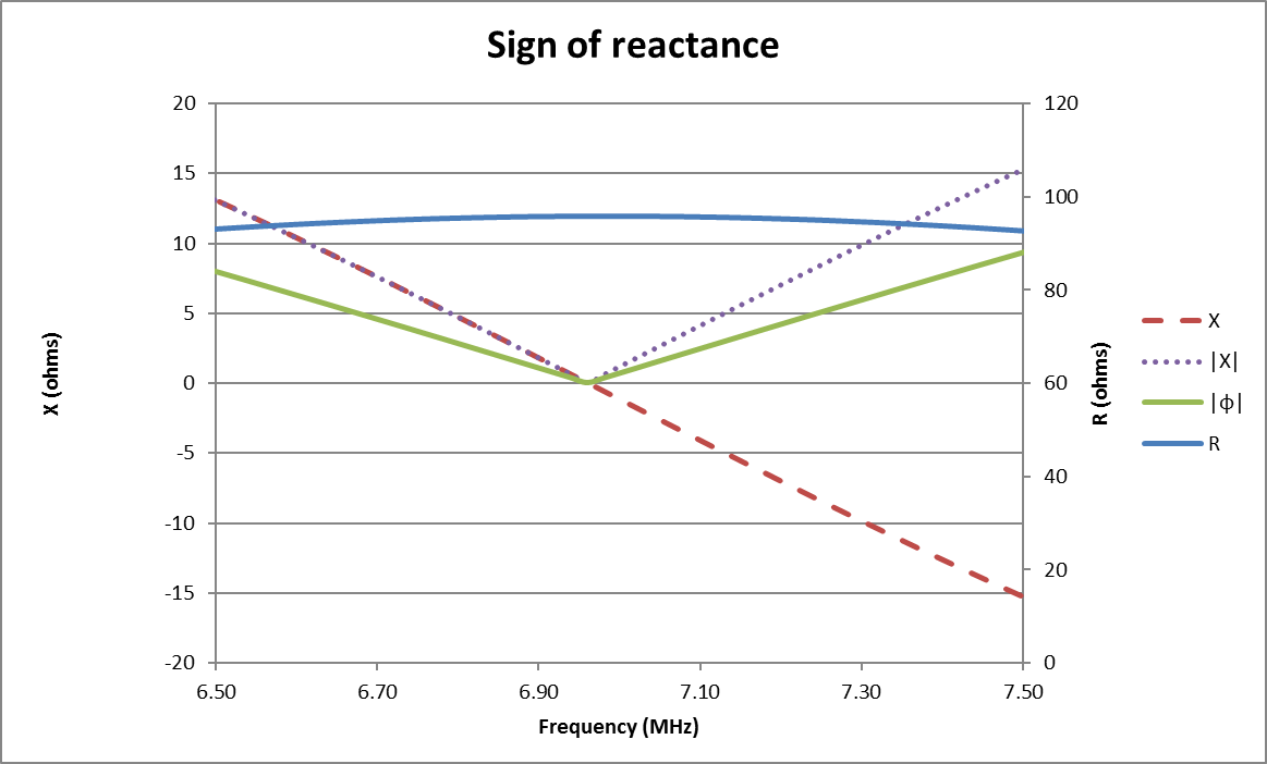
Above is the calculated R and X looking into 7m of Belden RG58C/U with a load 25+j0Ω. Also shown is |X|(as would be measured by the LP-100A) and calculated magnitude of phase of R,X, |φ|. Continue reading LP-100A impedance measurement

Rigexpert Antscope v4.3.1 released

It seems yet another new version of Rigexpert Antscope has been released, and it maintains the scale limits available for R,X plots to +/-2000Ω, it still does not allow the range permitted by v4.2.57 (+/-5000Ω).

No change details provided by Rigexpert.

Back to v4.2.57, though it is very likely it has undisclosed defects fixed in later releases.

Bottom line is that if you want an analyser with direct graphing of impedances over 2000Ω (eg measuring common mode choke impedance), think of a different analyser.