Measuring modulation index of an amplitude modulated wave with an oscilloscope

A oscilloscope can be used to measure the modulation index of an amplitude modulated wave. Modulation index is a value from 0 to `1, but is often expressed as a percentage.

The discussion here assumes symmetric modulation, it does not apply to super modulation schemes or any other schemes that are asymmetric.

Envelope method

If an oscilloscope is used to display the modulation envelope (as it is known), modulation index can be calculated from measured values of the peak voltage at the crest and valley of the envelope waveform.

Modulation index can be calculated as \(m=\frac{b-a}{b+a}\). Continue reading Measuring modulation index of an amplitude modulated wave with an oscilloscope

U.FL connectors – hints

This article expands on discussion at nanoVNA – that demo board and its U.FL connectors.

Before looking at the specifics of the Hirose U.FL connector, clean connectors work better and last longer. That should not be a revelation.

A can of IPA cleaner and a good air puffer are invaluable for cleaning connectors. The air puffer show  has a valve in the right hand end, it doesn’t suck the dirt and solvent out of the connector and blow it back like most cheap Chinese puffers, this one was harder to find and expensive ($10!). Continue reading U.FL connectors – hints

The need for infinite preamplifier gain?

A recent posting on social media kicked off some discussion about infinite gain preamplifiers, mostly in the context of an unloaded very short vertical.

Over the past couple of years I’ve had a number of comments and questions about active antennas, instigated by my ARRL book, Receiving Antennas for the Radio Amateur.

The “main ingredient” of an active antenna (in this discussion, we’ll center on the very short WHIP), is the preamplifier, which generally takes the form of an FET source follower.

A true source follower (or ideal cathode follower) is theoretically capable of INFINITE power gain). In practice, modern FET input op-amps have an input resistance on the order of a teraohm or so, and an input capacitance of about a picofarad.

Although we can’t QUITE get to infinite power gain with a real FET (or FET input op amp), we can get EXTREMELY high power gains. Assuming an output (source) resistance of 1Kohm and an input resistance of 1 teraohm, a voltage follower will have a power gain of 10^21:1…..not too shabby. (This is assuming essentially a DC signal, where the input parallel capacitance can be ignored).

At this point in time, there has been no mention of noise… but it is key to the problem. Continue reading The need for infinite preamplifier gain?

ESP WiFi relay project – update #1

ESP WiFi relay project – preview previewed a WiFi controllable relay board using commonly available low cost hardware from sources like eBay and Aliexpress.

The stimulus for the project is a remotely WiFi controllable relay for reset function in a remote controlled ham station, basically to recover operation of some system element by bouncing the power.

The information presented here applies to development v0.2.

Features:

  • support typical multi channel relay boards;
  • ESP8266 and ESP32 firmware versions;
  • WiFi credentials programmable via a captive web interface;
  • DHCP or static IP;
  • mDNS responder;
  • flexible configuration stored as json file in on-board LittleFS file system;
  • optional authentication to secure remote access.


Above is a ESP12F_Relay_30A X2_V1.1 relay board (~$20 inc shipping) deployed for field testing. This board has a switched mode power supply on board and will run on 7-28VDC. In this application, the AC circuit is wired through the NC contacts, and the relays are operated to break the power. Normal operation is with the relays released, and current consumption @ 13.8V is 30mA. Continue reading ESP WiFi relay project – update #1

WriteOptiBoot.bat

I have lots of projects across a range of microcontroller architectures where reliably programming a new instance of the target is required.

Using an IDE to compile and load, eg traditional / common use of the Arduino IDE, is not a path to that reliability.

A better approach is to save compiled binaries, and have a saved method of programming the chip, binary application code, EEPROM if needed, and hardware settings such as fuse bits, options etc.

Let’s look at an example,  a cmd file or bat file to program certain Arduino architecture boards with a customised Optiboot bootloader. Continue reading WriteOptiBoot.bat

USBasp – hints

The USBasp is a really useful and quit inexpensive ISP programmer that suits AVR 8 bit microcontrollers.

This article offers some hints on buying and using the USBasp.

There are lots of sellers of these on eBay, Aliexpress etc… but there are traps in buying them. I recall buying the USBasp with cable for less than $5, but they are more like double that now… or more

The adapters with the pogo pins are simply ordinary adapters with P75-xxx (eg P75-LM2) pogo pins inserted. Continue reading USBasp – hints

ISP programming of the (tr)uSDX

I noted some online discussions where some people had troubles using an ISP programmer to program the MCU.

I do not have a (tr)uSDX (trusdx), but inspection of the schematic does hint what those users are doing wrong.

Loading the SCK, MOSI and MISO lines risks problems with operation of the SPI protocol used, but the effect depends to some extent on the driver, length and type of interconnecting cable etc.

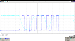
Here are some measurements of a USBasp driving an Arduino board with 5V Atmega328P 16MHz chip using about 200mm of ribbon cable… AND the MOSI line is loaded with a 0.01µF capacitor (as in the (tr)uSDX schematic).

As mentioned, ISCP uses an SPI protocol and the capture above uses blue for SCK and cyan for MOSI. Continue reading ISP programming of the (tr)uSDX

Switching times in Class-E RF power amplifiers

Class-E RF power amplifiers have become quite fashionable in ham radio in the last decade or two.

One of, if not the main contribution to efficiency in a Class-E RF amplifier is the operation of the active device in switching mode where it is either not conducting, or conducting hard (saturated, with very little voltage across it). Both of these are very low dissipation conditions, but in the transition between these states there is significant current and voltage present, the product of which gives significant instantaneous power… so the idea is to make this transition very fast so that the average power is low.

This article discusses effect of slowed switching times on PA efficiency.

Above is a circuit above is from (Sokal 2001) which explains the amplifier and gives guidance on selection of components. Continue reading Switching times in Class-E RF power amplifiers

NanoVNA-H4 – inductor challenge – part 7

One method described online on YouTube and in social media is the 90° method as I will call it.

The reason why people make measurements at +/- 90 degrees on the smith chart is because the measurement accuracy using the shunt configuration when trying to measure the nominal value of an inductor or capacitor is highest at 0+j50 ohms (or 0-j50 ohms… OD).

To be clear, this is the phase of s11 or Γ being + or – 90° as applicable.

Is there something optimal when phase of s11 is + or – 90°?

Does the software / firmware / hardware give significantly more accurate response under such a termination?

Above is a diagram from a HP publication, slightly altered to suit the discussion. Continue reading NanoVNA-H4 – inductor challenge – part 7

FNIRSI FNB48 USB meter – cable resistance measurement

The FNIRSI FNB48 USB meter is a flexible USB power meter that incorporates a facility to measure the resistance of a USB cable. The tested unit uses firmware v2.50.

The operation also needs a constant current load of 0.5 – 1A (for most cables).

The method is: Continue reading FNIRSI FNB48 USB meter – cable resistance measurement