Introduction
End Fed Half Wave antennas are again very fashionable with hams, accompanied by extraordinary claims and somewhat sparse understanding (the way of modern ham radio).
To add some light I have created a set of NEC 4.2 models of a half wave antenna on 20m to give some insight into the behaviour of a bottom fed vertical half wave over real ground.
This analysis does not consider harmonic operation, antennas are a half wave at 14.2MHz.
Four models are used:
- 20mHW-VEP – bottom fed vertical above perfect ground;
- 20mHW-VEA – bottom fed vertical above real ground;
- 20mHW-VCA – centre fed vertical above real ground (ie ground independent feed);
- 20mHW-HCA – centre fed horizontal at 5m height above ground;
NEC 4.2 model description:
- 14.2MHz;
- no conductor loss;
- real ground assumed to have conductivity=0.005S, εr=13, of course results are dependent on these values;
- conductors are ~10m long, 20mm diameter;
- bottom fed vertical half wave uses a 10m x 20mm vertical driven ground electrode;
- centre fed vertical is raised 200mm above ground;
- feed line and feed line common mode current are excluded;
- the centre of all antennas is ~5m above ground (real or perfect).
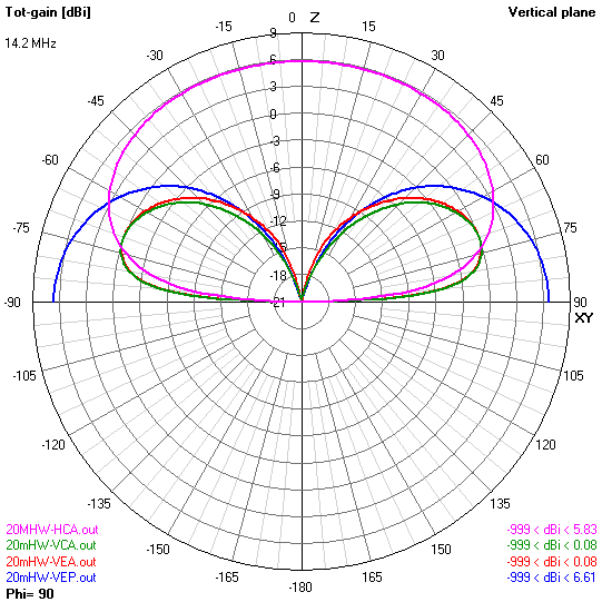
Above are the patterns from the models for discussion. Continue reading End fed half wave – NEC models for 20m