Ask half a dozen hams to define a Ground Plane Antenna and you will probably get half a dozen different answers, yet it is thought of as one of the basic antenna types that newcomers will be introduced to in their education.
There seems credible acceptance by some writers that the Ground Plane Antenna was invented by George Brown (more completely Brown, Lewis and Epstein (BLE)) from RCA, and is described in US Patent 2,234,333 for a Demountable Antenna
filed in 1939. The patent does not call the thing a Ground Plane Antenna, but it does describe what could be naively described as a quarter wave vertical radiator with four equally spaced quarter wave horizontal radials (plus some other embellishments).
BLE gives the dimensions for the antenna at 41.5MHz and offers that the feed point impedance is 21.5Ω, transformed up to (the then popular) 70Ω transmission line by his custom quarter wave transformer (part of the invention).
The naively basic Ground Plane Antenna
Lets look at an NEC model of the vertical quarter wave and four quarter wave radials alone (ie in free space).
An NEC-4.2 model gives the feed point impedance as 23.4+j6.11Ω. The reactance is not surprising since the elements are actually slightly longer than a free space quarter wave, and resonance would occur at a little less length. Importantly, the R value is in the ball park of their estimate, so that reconciles reasonable well. BLE do not give a gain figure, but the gain of a lossless model in NEC is 1.44dB.
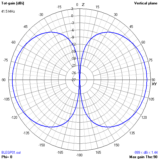
Above is the pattern, no surprises there (unless you were expecting it to look like a quarter wave monopole on perfectly conducting earth).
The Ground Plane Antenna with conductive mast (or feed line) near real ground
BLE hint the use of a conductive mast and coaxial feed line, and although some details of the connection appear ill-conceived, the conductive mast and ground are important elements that are present in most implementations, not only present but variable.
One online expert stated:
With a 1/4 wave vertical at least 1/4 wave high at the base (the classic minimal height for a GP), and 4 radials; the effect of ground is minimized, at 1/2 wave high the ground doesnt exist.
So, lets model it at double that height, 1λ above average ground (σ=0.005, εr=13).
Feed point impedance is 51+j12Ω.
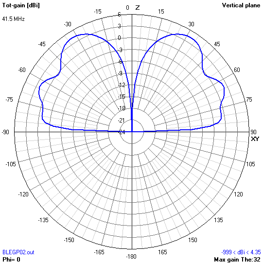
Above, gain in this scenario is 4.35dB.
Clearly, it is nothing like the free space pattern, gain, or feed point impedance… the online expert was talking nonsense (again).
Why is the antenna so different?
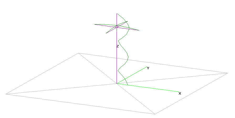
Above is the current distribution. Note that there is significant current flowing on the conductive mast (which is essentially the same as feed line common mode current in cause and effect).
It turns out that the antenna behaviour is very sensitive to this current, the conductor path, and the ground parameters… things that are implementation variables.
Now BLE recognised the feed line common mode current issue because on of the benefits they claimed was:
A further object is to provide an antenna which will not establish currents in the transmission line connected thereto.
They claimed it did this because of the shielding action of the four radials. Clearly it is not very effective and it is a claim without much (or any) foundation.
In fact it is very challenging to eliminate current on vertical masts and feed lines.
Nevertheless you will hear online experts explain you don’t need a common mode choke with a Ground Plane Antenna, don’t you understand, it is an unbalanced antenna, unbalanced just like your radio – no choke required.
It is easy to cotton on to these very naive concepts, and if you never confirm by measurement, you will be a believer… and there are lots of them in ham radio.
How many radials
There is a story that does the rounds in ham radio that Brown originally designed the antenna with just two opposing radials, and that Brown’s bosses at RCA inisted that customers would not accept that, it had to have four. The implication is that two are sufficient and in ham speak, the explanation goes that the currents in two opposing radials, flowing in opposite directions, cancel each other.
Well, it is true that the currents cancel each other completely… in the orthogonal plane that bisects the radial pair… the the cancellation is less than complete everywhere else. More paired radials provide more complete cancellation in the 3D space. Three equally spaced radials works, as do other numbers that are not powers of two, so long as they are evenly distributed, and the more the better the cancellation, but it is a case of diminishing returns.
If the anecodote was true, it would suggest that Brown’s bosses were better engineers… it seems unlikely.
Burying radials
Lot of people bury radials and still call the thing a Ground Plane Antenna. They commonly carefully measure the radial lengths to a formula so that they are an electrical quarter wave in free space… but they are not in free space, they are in soil which behaves like a lossy dielectric so if resonance is apparent (it can be masked by the loss), they are resonant at a much lower frequency due to the dielectric constant of the soil. Indeed the velocity factor of the radial in soil might be closer to 0.5 than unity, and a free space quarter wave might be close to an electrical half wave in the soil… more or less the opposite of what was intended.
Buried radials significantly alter the behaviour of the antenna in terms of Directivity, Gain and feed point impedance and one could argue that it lacks the essentials of a Ground Plane Antena and is therefore not a Ground Plane Antenna.
So… when someone is talking about a “ground plane antenna”, you need more information to really understand what they are talking about.