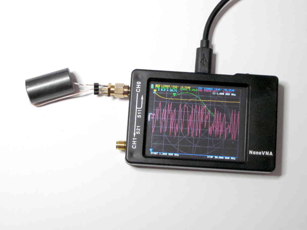
A very common design of a n:1 transformer for EFHW antennas uses a 2t primary on and FT240-43 (or even smaller) ferrite core.
In a process of designing a transformer, we often start with an approximate low frequency equivalent circuit. “Low frequency” is a relative term, it means at frequencies where each winding current phase is uniform, and the effects of distributed capacitance are insignificant.
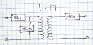
Above is a commonly used low frequency equivalent of a transformer. Z1 and Z2 represent leakage impedances (ie the effect of magnetic flux leakage) and winding conductor loss. Zm is the magnetising impedance and represents the self inductance of the primary winding and core losses (hysteresis and eddy current losses). Continue reading nanoVNA-H – measure equivalent core loss resistance
Last update: 14th April, 2024, 1:36 PM