Simple keyer with accurate timing for QRSS beacon
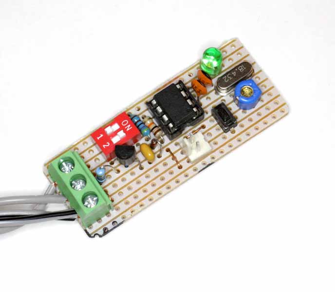
Continue reading Simple Morse beacon keyer for VK3FI on 600m
Continue reading Simple Morse beacon keyer for VK3FI on 600m
This series of seven articles has:
Continue reading Designing high performance VHF/UHF receive systems – Part 7
G/T can be measured using celestial noise sources provided the antenna can be pointed to them. The noise source that is most appropriate will depend on expected G/T, frequency, time etc.
Continue reading Designing high performance VHF/UHF receive systems – Part 6
This part explains how to build a model of the entire receive system to calculate G/T.
Firstly, make an inventory of all of the system elements that you intend to model.
A model needs to be no more detailed than is necessary to provide adequate accuracy for the purpose at hand.
Continue reading Designing high performance VHF/UHF receive systems – Part 5
We have explained how to calculate Teq from Noise Figure, but most transceiver specifications do not give Teq or Noise Figure directly, in fact they don’t really contain sufficient information to reliably calculate Teq or Noise Figure.
Credible equipment reviews might provide an estimate of Noise Figure or Teq.
The best approach is to directly measure Noise Figure using a known noise generator and the Y Factor Method.
Continue reading Designing high performance VHF/UHF receive systems – Part 4
In the last part, the meaning of the equivalent noise temperature of an amplifier was given.
Whilst you will find that working in Teq has advantages for this analysis, amplifier specifications may not give Teq, but may give Noise Figure.
Continue reading Designing high performance VHF/UHF receive systems – Part 3
G/T is defined as the ratio of antenna gain to total equivalent noise temperature.
For clarity, lets define those terms.
Gain of an antenna is defined (IEEE 1983) as the ratio of the radiation intensity, in a given direction, to the radiation intensity that would be obtained if the power accepted by the antenna were radiated isotropically. (Isotropically simply means equally in all directions.)
Continue reading Designing high performance VHF/UHF receive systems – Part 2
There is a seemingly endless series of articles on small transmitting loops on the cheap.
(eHam 2014) is another, it describes a so-called magnetic loop for transmitting on 14.2Mhz using 4.57m of 2.6mm copper wire for the main loop. The author reports the bandwidth of the finished antenna as 100kHz. One of the claimed benefits is that with such wide bandwidth, a variable tuning capacitor is not required.
A metric that may be used to express the performance of an entire receive system is the ratio of antenna gain to total equivalent noise temperature, usually expressed in deciBels as dB/K. G/T is widely used in design and specification of satellite communications systems.
G/T=AntennaGain/TotalNoiseTemperature 1/K
Example: if AntennaGain=50 and TotalNoiseTemperature=120K, then G/T=50/120=0.416 1/K or -3.8 dB/K.
Continue reading Designing high performance VHF/UHF receive systems – Part 1
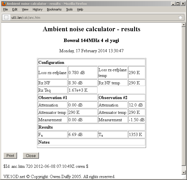
I made a measurement of ambient noise on 144MHz this morning using the technique described at (Duffy 2009).
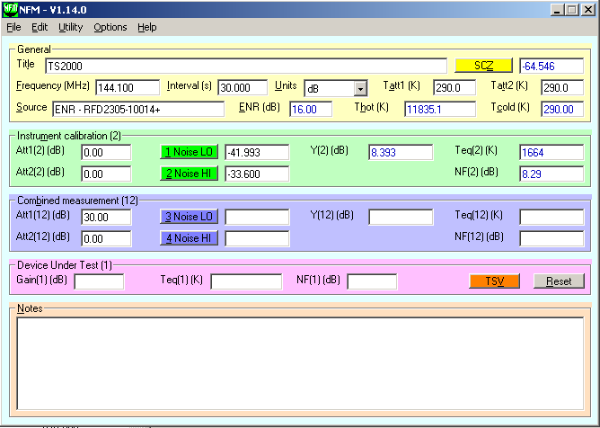
First step is to recheck the NF of the receiver. The TS2000 is getting a little tired, NF=8.3dB.
The technique calculates ambient noise from the variation in receiver output noise of a receiver of known Noise Figure with the insertion of a known input attenuator. The receiver output noise was measured using NFM (Duffy 2007) which allowed integration over 20s for high resolution measurement.
 Continue reading VK2OMD ambient noise measurement 144MHz – 20140217