Ellington 3 x FT240-52 matching transformer for an EFHW

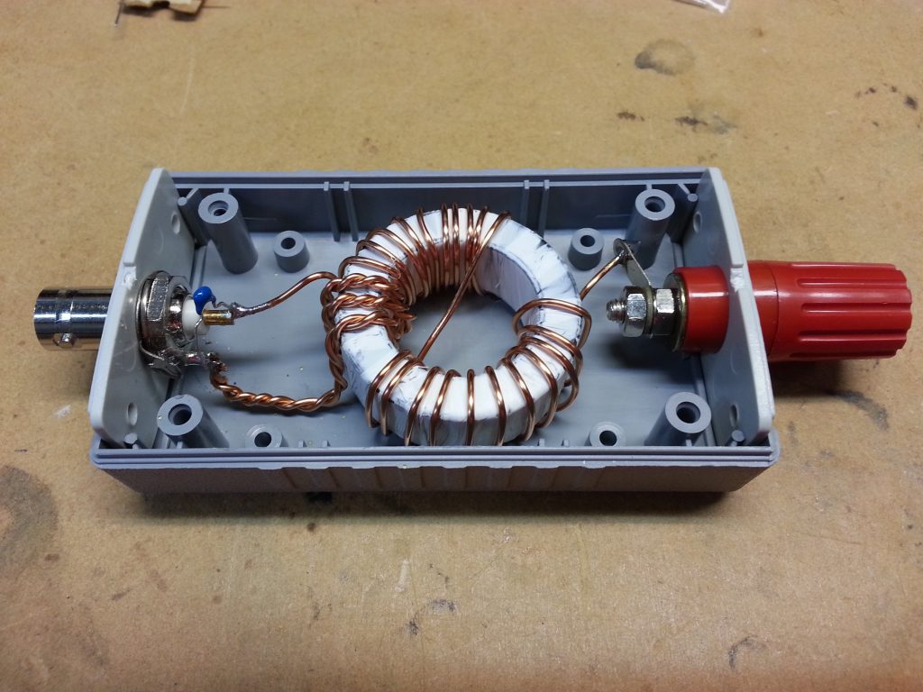
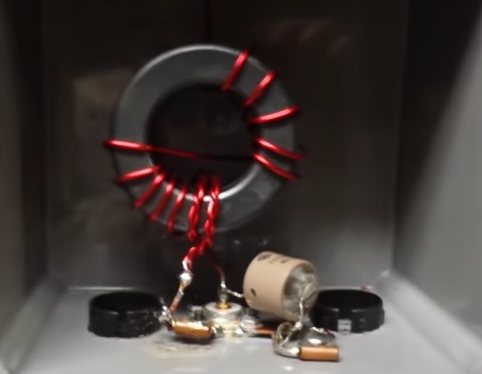
Ellington describes in a Youtube video his high power matching transformer for an EFHW, he rates it suited to 500W CW.

Like almost all such ‘designs’, they are published without supporting measurements or simulations.

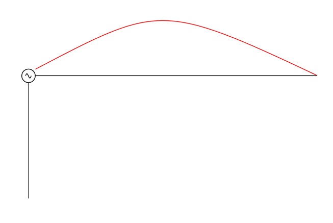
The transformer is intended to be used with a load such that the input impedance Zin is approximately 50+j0Ω, Gin=0.02S.

Analysis of a simple model of the transformer with a load such that input impedance is 50+j0Ω gives insight into likely core losses.
Continue reading Ellington 3 x FT240-52 matching transformer for an EFHW

PD7MAA’s BN43-202 matching transformer for an EFHW – full measurement set

I have written some recent articles about or relevant to PD7MAA’s BN43-202 EFHW matching transformer. At about the same time a discussion started on and through that discussion, one ‘online extra expert’ stated that my analysis was bogus (dictionary meaning: not genuine, faked, a misrepresentation).

This article presents detail that was not included in the earlier articles as it distracts from the issue for most readers. Continue reading PD7MAA’s BN43-202 matching transformer for an EFHW – full measurement set

Common failings of EFHW matching transformers

I have written many reviews of published EFHW matching transformers, and in most cases the reviews have reported estimated or measured losses that are appalling and not disclosed by the ‘designers’.

Why is it so?

I am asked, why is it so?

Up front, I do not know the answer definitively, but let me offer some thoughts based on the designer’s own articles and discussions by ‘online experts’.

Apparent reasons include:

  1. lack of understanding of ferrite and powdered iron core material behaviour;
  2. lack of understanding of coupled coils, and mutual inductance;
  3. use of inductor design tools that are inadequate at radio frequencies;
  4. lack of competency in basic linear circuit theory analysis for AC circuits;
  5. failure to make meaningful measurements of the built article;
  6. focus on input VSWR as a single metric indicating goodness;
  7. reliance on QSOs for evidence of performance;
  8. an attitude that antenna system radiation efficiency doesn’t matter, particularly for QRP (if the term antenna system radiation efficiency is even understood as a quantitative metric).

Continue reading Common failings of EFHW matching transformers

PD7MAA’s BN43-202 matching transformer for an EFHW – measurement of a prototype

At PD7MAA’s BN43-202 matching transformer for an EFHW I gave an estimate of the core loss in PD7MAA’s transformer.

This article reports measurement of a prototype built to his design.


Above is PD7MAA’s graphic for his transformer. It is a little confusing as an 11t wind will start and finish with ends as the blue wind, so the red winding must have and odd number of half turns which suggests the windings are actually 1t and 5.5t (pity he did not show a picture of the real transformer).

PD7MAA gives some measurements for his transformer with a 3300Ω load, but he does not give loss measurements. This experiment is to replicate his configuration, measure the loss and compare it to the estimate given at PD7MAA’s BN43-202 matching transformer for an EFHW.

The prototype uses 1t primary and 5.5t secondary. The secondary load is a 3300Ω resistor in series with the VNA 50Ω input port.

Above is a screen shot of a sweep from 6 to 8MHz. The key data is that shown for the marker at 7.1MHz. Continue reading PD7MAA’s BN43-202 matching transformer for an EFHW – measurement of a prototype

PD7MAA’s BN43-202 matching transformer for an EFHW

End Fed Half Waves have certainly captured the minds of QRP aficionados, and there is a steady stream of ‘designs’ appearing on the ‘net.

A recent article by PD7MAA describes such a transformer using a BN43-202 balun core for up to 20W PEP from 7-29MHz.

Above is PD7MAA’s graphic for his transformer. It is a little confusing as an 11t wind will start and finish with ends as the blue wind, so the red winding must have and odd number of half turns which suggests the windings are actually 1t and 5.5t (pity he did not show a picture of the real transformer). Let’s proceed under that assumption. Continue reading PD7MAA’s BN43-202 matching transformer for an EFHW

End fed matching – VK3IL design on LO1238

A correspondent asked about the use of a Jaycar LO1238 ferrite core in VK3IL’s EFHW matching unit for 40m and up. The LO1238 implementation would use 3t primary and 24t secondary on the core.

If the transformer is simply used without an ATU between it and the radio, and we assume that the antenna system is adjusted to present low VSWR50 to the radio, a simple approximation involves calculating the magnetising admittance of the 3t 50Ω winding, and calculating the portion of total input power that is dissipated in that admittance.

Using the calculator at Calculate ferrite cored inductor, the admittance (G+jB) of the 3t winding is 0.00177-j0.00204S. (The impedance of a sample wind could be measured with a suitable analyser and converted to admittance.) Continue reading End fed matching – VK3IL design on LO1238

End Fed Half Wave / Inverted L / Half Wave Dipole

The popular End Fed Half Wave is all things to all men, but this article compares an End Fed Half Wave, Inverted L, and Half Wave Dipole with some common parameters:

  • frequency: 7.1MHz;
  • flat top length: 20m;
  • Height above ‘average’ ground (σ=0.005, εr=13): 10m;
  • lossless balun / matching device.

Key differences:

  • ground connection: Inverted L = 2Ω, End Fed Half Wave = 100Ω; and
  • effective common mode choke used on the dipole.


Clip 202

Above is the modelled gain for all three. Continue reading End Fed Half Wave / Inverted L / Half Wave Dipole

The magic of the End Fed Half Wave antenna / EFHW

I have noted recently the increasing popularity of the so-called End Fed Half Wave antenna, though the term often includes harmonic operation of the antenna.

It seems that at the heart of common ham understanding of this antenna system is that some kind of two terminal feed device creates a scenario with current on the nominal radiator, and zero common mode current on the feed line. If that feed device is small, its contents bears little influence on the current distribution on the feed line and radiator (the device behaviour approaches that of a simple circuit node).

Screenshot - 21_06_16 , 14_55_56Above is the kind of current distribution envisaged by many. The equivalent source is shown at the end fed feed point The red curve is the magnitude of current, the horizontal line represents the nominal radiator, and the vertical line represents the common mode conductor formed by the feed line. The feed line is often of arbitrary length, arbitrary route, and it may connect to real ground via an arbitrary impedance. Pretty much everything about this antenna system is random save the length of the nominal radiator. Continue reading The magic of the End Fed Half Wave antenna / EFHW

Thinking about SOTA, EFHW and EMR safety

There seems to have been a revival in use of the so-called End Fed Half Wave antenna.

The prospect that a small radio such as the FT817, a magic match box and 10m of wire makes a good 20m field station appeals to many a SOTA enthusiast.

Let us model a scenario with a FT817 powered by internal battery and sitting on an insulating platform (eg a pack) 0.3m above natural ground, a 10m wire strung up into a tree at a 45° angle, and a 1m long mic cord stretched up at 45° in the other direction. The is the popular so-called ‘no counterpoise’ configuration.

A simplified model of just the current paths without regard to the bulk of the radio, or the effect of the helix of the mic cord illustrates an approximate current distribution. The model uses 1W RF input to the antenna over ‘average ground’ (σ=0.005, εr=13).


Clip 142

Above is a plot of the current distribution. Current is a minimum at the open ends, a boundary condition for the problem, and maximum in the middle of the half wave. We expect H field to be greatest near the current maximum, and E field to be greatest near the current minima. Continue reading Thinking about SOTA, EFHW and EMR safety

End fed matching – analysis of VK3IL’s measurements

David, VK3IL posted EFHW matching unit in which he describes a ferrite cored transformer matching unit that is of a common / popular style.

My EFHW match box. 3:24 turns ration on a FT140-43 toroid with a 150pF capacitor across the input.

Above is David’s pic of his implementation. It is a FT140-43 toroid with 3 and 24t windings and note the 150pF capacitor in shunt with the coax connector.

The popular belief is that these are a broadband impedance transformer with impedance ratio equal to the square of the turns ratio, 64 in this case and therefore a broad band match from 3200Ω to 50Ω.

To his credit, David took some measurements of several different variations and reported them in his article.

Clip 135

Above are David’s measurements of the subject transformer.

Lets explore the matching detail for the case of a 3.3kΩ load at 22MHz, and using the 150pF shunt cap.

Superficially, you might convince yourself that this is explained by the turns squared story, but the 150pF doesn’t reconcile with that story, nor does the variation with frequency, eg the rapid change above 22MHz. Continue reading End fed matching – analysis of VK3IL’s measurements