This article presents a simple way to make measurements of a prototype Guanella 1:1 current balun, measurements that can guide refinement of a design.
The usual purpose of these transmitting Guanella 1:1 current baluns is to reduce common mode feed line current. Not surprisingly, the best measure of a device’s effectiveness is direct measurement of common mode current (it is not all that difficult), but surprisingly, it is rarely measured.
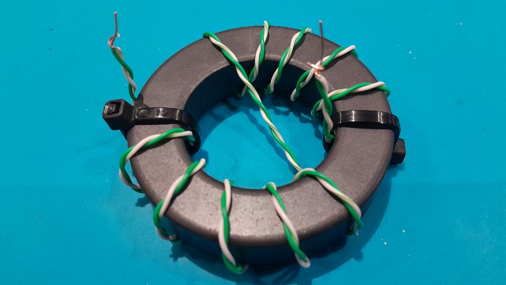
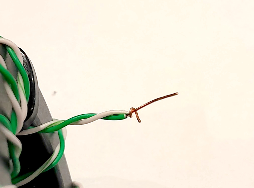
Above is the prototype transformer being a Fair-rite 5943003801 (FT240-43) wound with 11t of solid core twisted pair stripped from a CAT5 solid core LAN cable and wound in Reisert cross over style. Note that Amidon #43 (National Magnetics Groups H material) is significantly different to Fair-rite #43.
There is no need to wind a prototype using expensive materials, the measurements made with the above prototype are very useful in guiding development without wasting expensive materials. Further, the measured results are very close to the behavior of the ‘raw’ balun.
s21, s11 measurement of through transmission
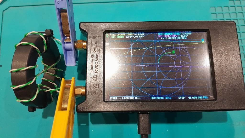
Above is the configuration for the through test, the clothes pegs are used to clamp one conductor to the outside of the SMA jacks, the inner wire is poked into the inner pin, the VNA is sitting on a cardboard box, the whole thing is on a wooden table. An alternative to the clothes pegs are small zip ties.
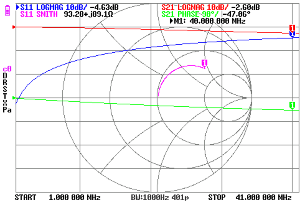
Above is a screenshot from the NanoVNA of the through measurement. The relevant traces are s11 Logmag, S11 Smith, and S21 Logmag.
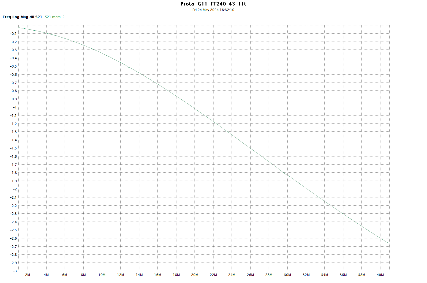
Above is an expanded graph of |s21|. At first glance, you might be horrified by the value of -1.8dB @ 30MHz. Many would assert that this shows a loss of 1.8dB… but more correctly it is InsertionLoss of 1.8dB and conversion of RF energy to heat is likely to be less.
See Measurement of various loss quantities with a VNA for discussion of Loss terms.
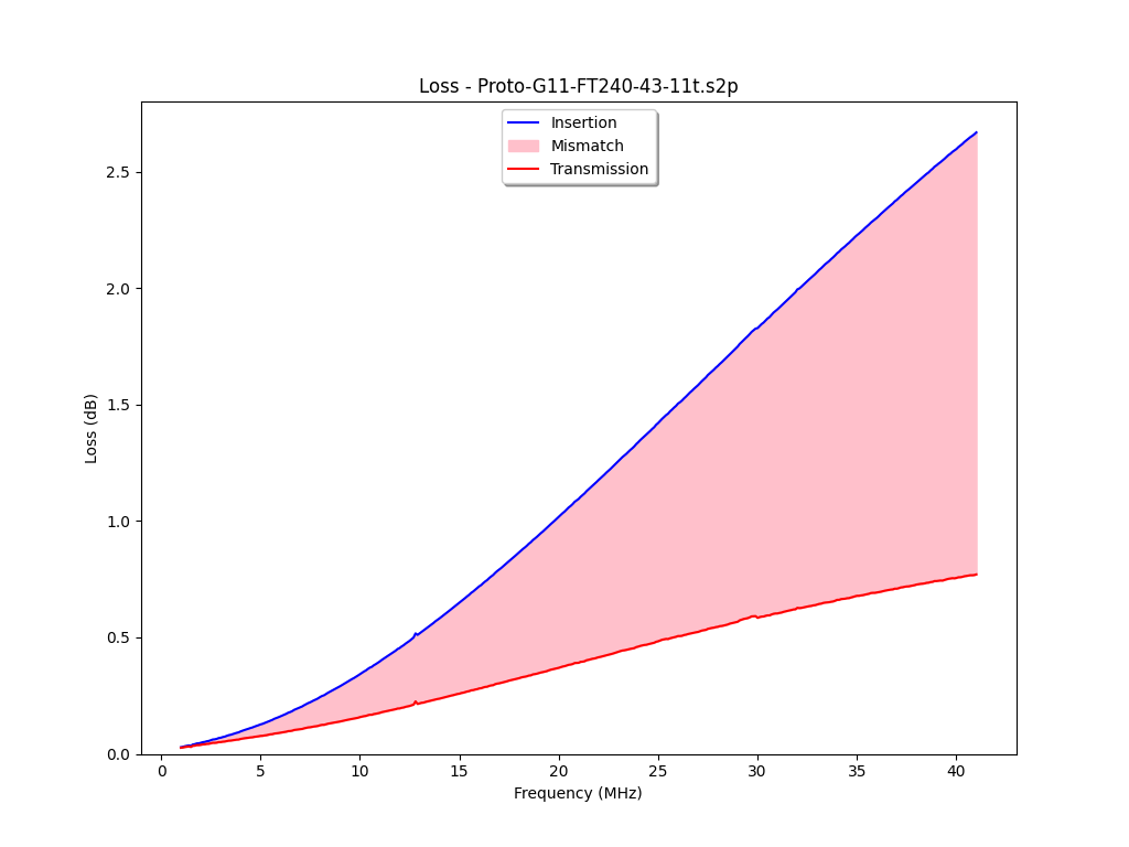
Above is a graph disaggregating InsertionLoss into (Transmission) Loss and MismatchLoss. Thicker conductors will have less Loss, and would be used in practical baluns.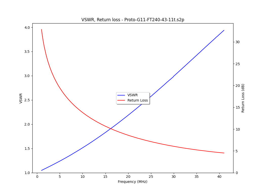
Above is a graph showing InsertionVSWR wrt 50Ω and ReturnLoss wrt 50Ω.
The significant mismatch is due to the fact that the balun introduces about 800mm of transmission line with Zo around 100Ω.
If you want low InsertionVSWR wrt some reference Zo, then the transmission line (the twisted pair or coax) needs to be that same Zo.
Is the InsertionVSWR and associated impedance transformation a problem? Well if you are using an ATU, it should not matter, and imperfection is dealt with by the ATU.
s11 reflection measurement of Zcm
Above, the DUT was reconfigured for Zcm measurement by twisting the white wire around the green wire at each end to bond them, leaving a short straight section of the green wire for connection. One end is inserted into Port 1 jack inner, the other was clamped to the male threads of Port 2, ie grounded.
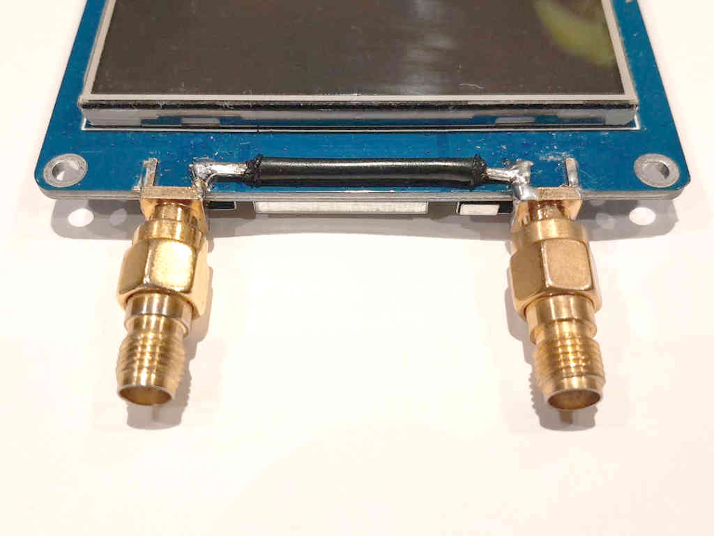
Note: my NanoVNA-H4 has been modified by addition of a short direct wire between the ground side of Port 1 and Port 2 jacks inside the case (see above).
(If wound with coax, Zcm measurements are made between shield ends, ignore the inner conductor.)
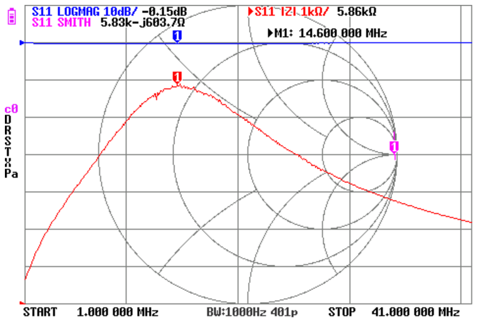
Above is a screenshot of the Zcm measurement, |Zcm| peaks at about 14.6MHz.
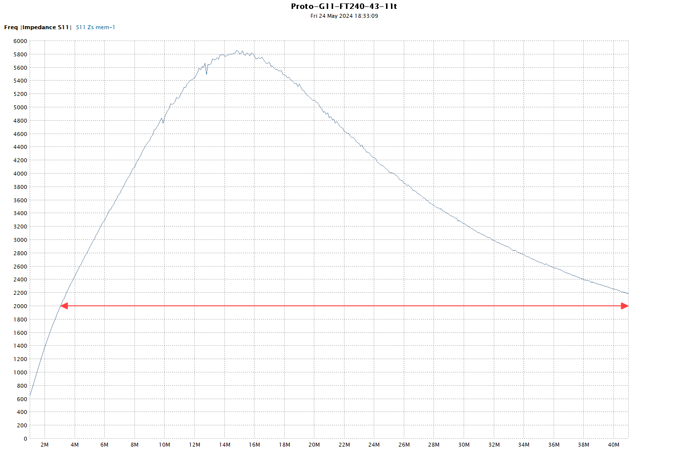
Above is a plot of |Zcm| taken from the .s1p file saved during measurement. |Zcm| > 2000Ω from 3MHz to more than 40 MHz.
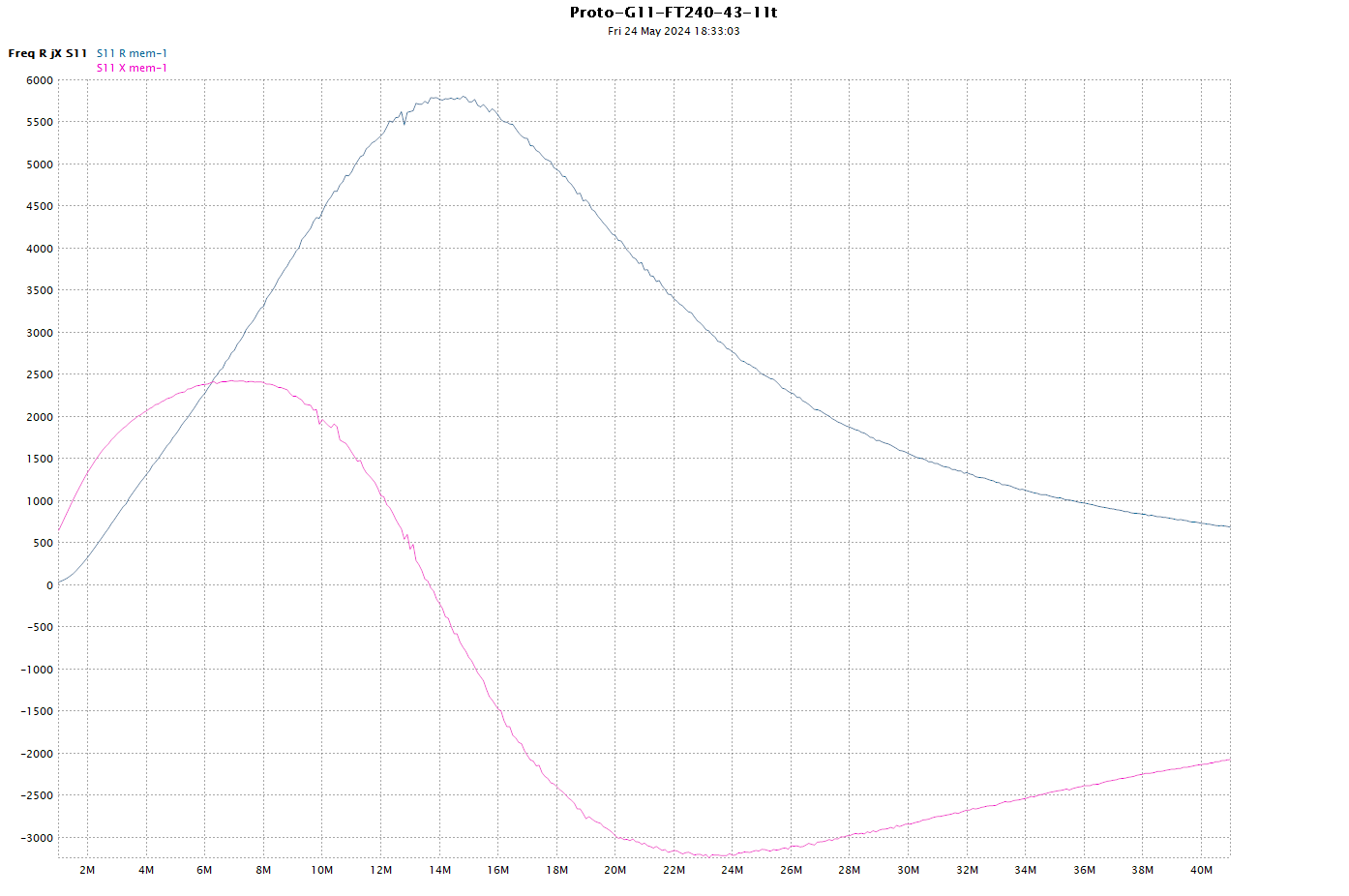
Above is a plot of the R and X components of Zcm taken from the .s1p file saved during measurement.
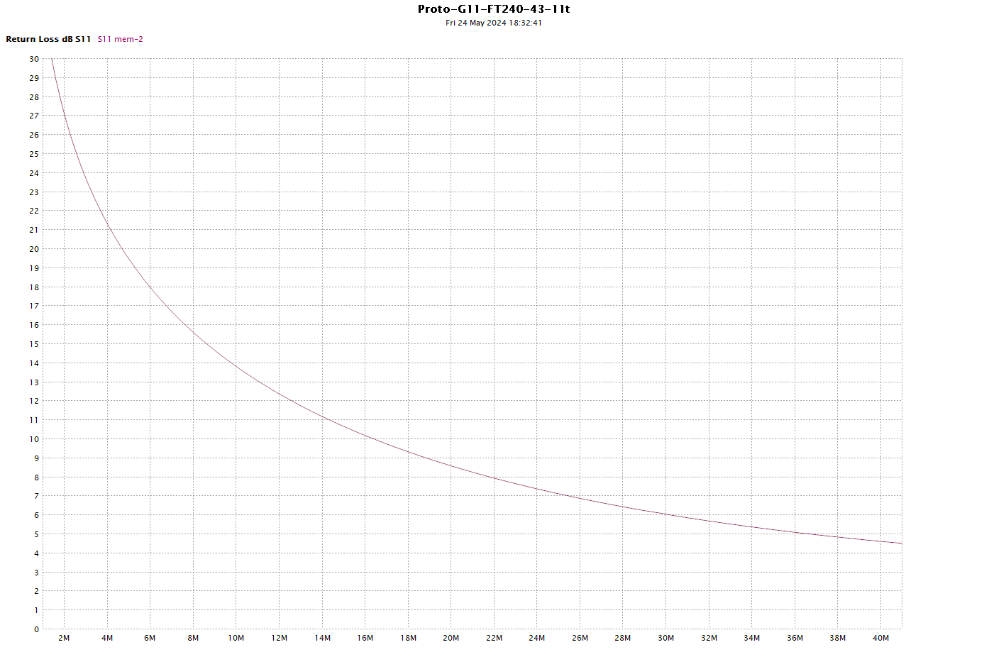
Above is a plot of the ReturnLoss taken from the .s1p file saved during measurement.
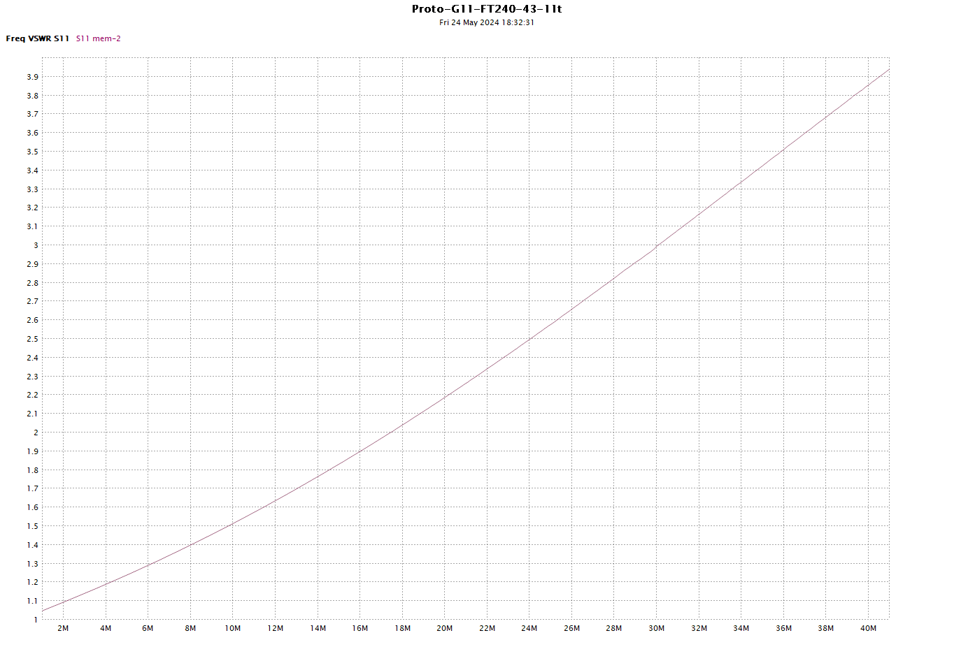
Above is a plot of the InsertionVSWR taken from the .s1p file saved during measurement.
Conclusions
Good / valid measurements of a prototype Guanella 1:1 balun can easily be made with a NanoVNA using low cost materials in capable hands.
Keep in mind that you are measuring a sample of one or a small number and that ferrite has a wide tolerance specification, and is temperature sensitive.
Experimenting with measurement setups and prototypes is the beginning of understanding of these things, more so that soaking up the utterings of armchair experts.
Go build and measure some prototypes, try different cores, different turns, different winding layouts, twisted / untwisted / coax etc.